ICMP Redirects - How Data Plane Traffic Can Become Control Plane Traffic
Note: If you are not familiar with the concepts of the data plane and control plane on network devices, I highly recommend reviewing my Understanding the Data, Control, and Management Planes of Network Devices post prior to reading this post. If you are not familiar with the concept of CoPP (Control Plane Policing) and how it can introduce packet loss for control plane traffic, I highly recommend reviewing my Understanding Control Plane Packet Loss due to CoPP post prior to reading this post.
Network engineers often like to categorize a traffic flow as either data plane traffic, or control plane traffic. Under this framework, traffic is either data plane or control plane, it cannot be both. However, in reality, data plane traffic can become control plane traffic, which can cause increased latency or packet loss for the data plane traffic. In this post, we’ll explore how this is possible.
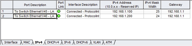
First, let’s get familiar with our topology. We have a Cisco Nexus switch connected to two traffic generators via physical interfaces Ethernet1/45 and Ethernet1/46. One traffic generator mimics a host named Host-1 with an IP address of 192.168.1.100, while the other traffic generator mimics a host named Host-2 with an IP address of 192.168.1.200.
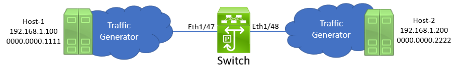
The switch has an SVI (Switched Virtual Interface) in VLAN 1 with an IP address of 192.168.1.1. This is a /24 subnet.
1
2
3
4
5
6
7
8
9
10
11
12
13
14
15
16
Switch# show ip interface brief

IP Interface Status for VRF "default"(1)
Interface            IP Address      Interface Status
Vlan1                192.168.1.1     protocol-up/link-up/admin-up
Switch# show running-config interface Vlan1

!Command: show running-config interface Vlan1
!Running configuration last done at: Sun Nov 21 16:53:53 2021
!Time: Sun Nov 21 16:55:06 2021

version 9.3(8) Bios:version 01.05

interface Vlan1
  no shutdown
  ip address 192.168.1.1/24
Both traffic generators are connected to the switch via access switchports in VLAN 1.
1
2
3
4
5
6
7
8
9
10
11
12
13
14
15
16
17
Switch# show spanning-tree vlan 1

VLAN0001
  Spanning tree enabled protocol rstp
  Root ID    Priority    32769
             Address     b08b.d00a.97f3
             This bridge is the root
             Hello Time  2  sec  Max Age 20 sec  Forward Delay 15 sec

  Bridge ID  Priority    32769  (priority 32768 sys-id-ext 1)
             Address     b08b.d00a.97f3
             Hello Time  2  sec  Max Age 20 sec  Forward Delay 15 sec

Interface        Role Sts Cost      Prio.Nbr Type
---------------- ---- --- --------- -------- --------------------------------
Eth1/47          Desg FWD 2         128.185  P2p
Eth1/48          Desg FWD 2         128.189  P2p
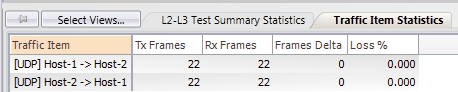
In this topology, there are two UDP traffic flows. One is from Host-1 to Host-2, and the other is from Host-2 to Host-1. Both traffic flows send a single packet per second. At the moment, there is no packet loss for either flow.
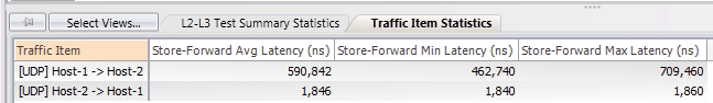
However, if we look at latency statistics for each traffic flow, we can see that the traffic flow from Host-1 to Host-2 has significantly higher latency (~0.6 milliseconds, or 6,000 microseconds) compared to the traffic flow from Host-2 to Host-1 (~2 microseconds).
This particular Nexus switch is a Nexus 93180YC-FX. The data sheet for this switch suggests that this model of switch has sub-microsecond port-to-port latency capabilities:
“The Cisco Nexus 93180YC-FX Switch (Figure 4) is a 1RU switch with latency of less than 1 microsecond that supports 3.6 Tbps of bandwidth and 1.4 bpps.”
The fact that the traffic flow from Host-1 to Host-2 has significantly higher latency than advertised suggests something is going on with this traffic flow. Let’s investigate further by using the Embedded Logic Analyzer Module (ELAM) troubleshooting tool to dig into the ASIC’s forwarding decision for a packet within this traffic flow.
1
2
3
4
5
6
7
8
9
10
11
12
13
14
15
16
17
18
19
20
21
22
23
24
25
26
27
28
29
30
31
32
33
34
35
36
37
38
39
40
41
42
43
44
45
46
Switch# debug platform internal tah elam asic 0
Switch(TAH-elam)# trigger init
Slot 1: param values: start asic 0, start slice 0, lu-a2d 1, in-select 6, out-select 0
Switch(TAH-elam-insel6)# set outer ipv4 src_ip 192.168.1.100 dst_ip 192.168.1.200
Switch(TAH-elam-insel6)# start
Switch(TAH-elam-insel6)# report
SUNDOWN1 ELAM REPORT SUMMARY
slot - 1, asic - 0, slice - 0
============================

Incoming Interface: Eth1/45
Src Idx : 0xb1, Src BD : 1
Outgoing Interface Info: dmod 1, dpid 25
Dst Idx : 0xb5, Dst BD : 1

Packet Type: IPv4

Dst MAC address: B0:8B:D0:0A:97:F3
Src MAC address: 00:00:00:00:11:11

Sup hit: 1,  Sup Idx: 3561

Dst IPv4 address: 192.168.1.200
Src IPv4 address: 192.168.1.100
Ver     =  4, DSCP    =    0, Don't Fragment = 0
Proto   = 17, TTL     =   64, More Fragments = 0
Hdr len = 20, Pkt len =  238, Checksum       = 0xf582

L4 Protocol  : 17
UDP Dst Port : 50000
UDP Src Port : 25000

Drop Info:
----------

LUA:
LUB:
LUC:
LUD:
  IP_SELF_FWD_FAIILURE
Final Drops:

vntag:
vntag_valid    : 0
vntag_vir      : 0
vntag_svif     : 0
This output has three important pieces of information:
- The
Dst MAC addressline indicates the Ethernet header of this packet is addressed to a MAC address assigned to the SVI of the switch, not the MAC address of Host-2 (0000.0000.2222) even though both hosts are (theoretically) in the same subnet. - The
SUP hitline implies the ASIC is punting this packet from the data plane to the control plane. - The
IP_SELF_FWD_FAIILURE[sic] flag under theLUDsection gives us a hint as to why the switch is punting this packet from the data plane to the control plane.
The outgoing interface information present in this output suggests that the switch will eventually forward the packet out of Ethernet1/46 (which can be proven through the show system internal ethpm info all command), but the index corresponding with the supervisor hit (which can be decoded through the show system internal access-list sup-redirect-stats command) suggests there’s an exception causing this packet to be punted.
1
2
3
4
5
Switch# show system internal ethpm info all | include dmod=1,dpid=25
  IF_STATIC_INFO: port_name=Ethernet1/46,if_index:0x1a005a00,ltl=5964,slot=0, nxos_port=180,dmod=1,dpid=25,unit=0,queue=65535,xbar_unitbmp=0x0,ns_pid=255,slice_num=0,port_on_slice=25,src_id=50

Switch# show system internal access-list sup-redirect-stats | include 356
    3560                         FWD Drop or MTU Exception    449
If we review CoPP statistics on this switch with the show policy-map interface control-plane command, we can see that there are non-zero transmission statistics under the “copp-system-p-class-exception” class.
1
2
3
4
5
6
7
8
9
10
11
12
13
14
15
16
17
18
19
20
21
Switch# show policy-map interface control-plane class copp-system-p-class-exception
Control Plane

  Service-policy  input: copp-system-p-policy-strict

    class-map copp-system-p-class-exception (match-any)
      match exception ip option
      match exception ip icmp unreachable
      match exception ipv6 option
      match exception ipv6 icmp unreachable
      set cos 1
      police cir 150 kbps , bc 32000 bytes
      module 1 :
        transmitted 154200 bytes;
        5-minute offered rate 260 bytes/sec
        conformed 315 peak-rate bytes/sec
          at Sun Nov 21 20:32:29 2021

        dropped 0 bytes;
        5-min violate rate 0 byte/sec
        violated 0 peak-rate byte/sec
Finally, if we use the Ethanalyzer control plane packet capture tool and filter it on packets sourced from or destined to 192.168.1.100 with the ethanalyzer local interface inband display-filter ip.addr==192.168.1.100 limit-captured-frames 0 command, we see two types of packets:
- The UDP data plane traffic sourced from Host-1 (192.168.1.100) destined to Host-2 (192.168.1.200), which is being punted to the control plane by the switch.
- ICMP Redirect packets sourced from the switch’s SVI (192.168.1.1) destined to Host-1 (192.168.1.100)
1
2
3
4
5
6
7
8
9
10
11
12
13
14
15
16
17
Switch# ethanalyzer local interface inband display-filter ip.addr==192.168.1.100 limit-captured-frames 0
Capturing on inband
2021-11-21 20:45:27.872463 192.168.1.100 -> 192.168.1.200 UDP Source port: 25000  Destination port: 50000
2021-11-21 20:45:27.872833  192.168.1.1 -> 192.168.1.100 ICMP Redirect (Redirect for host)
2021-11-21 20:45:27.872895 192.168.1.100 -> 192.168.1.200 UDP Source port: 25000  Destination port: 50000
2021-11-21 20:45:28.872503 192.168.1.100 -> 192.168.1.200 UDP Source port: 25000  Destination port: 50000
2021-11-21 20:45:28.872938  192.168.1.1 -> 192.168.1.100 ICMP Redirect (Redirect for host)
2021-11-21 20:45:28.873010 192.168.1.100 -> 192.168.1.200 UDP Source port: 25000  Destination port: 50000
2021-11-21 20:45:29.872495 192.168.1.100 -> 192.168.1.200 UDP Source port: 25000  Destination port: 50000
2021-11-21 20:45:29.872945  192.168.1.1 -> 192.168.1.100 ICMP Redirect (Redirect for host)
2021-11-21 20:45:29.873006 192.168.1.100 -> 192.168.1.200 UDP Source port: 25000  Destination port: 50000
2021-11-21 20:45:30.872495 192.168.1.100 -> 192.168.1.200 UDP Source port: 25000  Destination port: 50000
2021-11-21 20:45:30.872912  192.168.1.1 -> 192.168.1.100 ICMP Redirect (Redirect for host)
2021-11-21 20:45:30.872984 192.168.1.100 -> 192.168.1.200 UDP Source port: 25000  Destination port: 50000

12 packets captured
Switch#
Note: The above packet capture shows each UDP data plane packet twice for each ICMP Redirect message. This is because when the Ethanalyzer tool is run with the
inbandkeyword, it captures packets entering or exiting the control plane. The first UDP data plane packet is shown as it enters the control plane through the supervisor’s inband interface after being punted from Ethernet1/45, while the second UDP data plane packet is shown as it exits the control plane through the supervisor’s inband interface after being forwarded by the software of the switch towards Ethernet1/46.
It’s now clear what’s going on here. The switch is punting this traffic from the data plane to the control plane because it meets ICMP Redirect conditions. This behavior is described in more detail in Cisco’s Understanding ICMP Redirect Messages article written by my friend and colleague Nikolay Kartashev. Recall that the data plane is designed to forward traffic going through the network device at high speeds with low latency. Generally speaking, the data plane is not designed to craft packets sourced by the network device itself - that responsibility lies with the control plane. Therefore, the data plane must punt this packet to the control plane so that the control plane can create an ICMP Redirect packet to be sent back towards the source of this traffic.
Thus far, the only symptom of this issue we’ve seen is high latency. However, another possible symptom you may observe as a result of this issue is packet loss. At the moment, our traffic flow is only 1 packet per second, which is very slow compared to a real traffic flow.
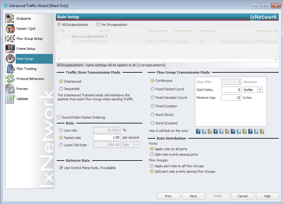
Let’s increase the speed of this traffic flow from 1 packet per second to 1,000 packets per second.
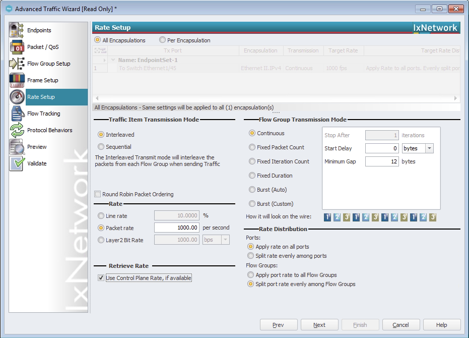
Now, we can see that the traffic flow from Host-1 to Host-2 has a significant amount of packet loss.
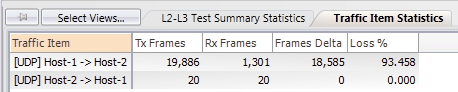
If we re-check our CoPP statistics, we can now see drops under the copp-system-p-class-exception CoPP class. This is the root cause of the packet loss observed in this traffic flow.
1
2
3
4
5
6
7
8
9
10
11
12
13
14
15
16
17
18
19
20
21
Switch# show policy-map interface control-plane class copp-system-p-class-exception
Control Plane

  Service-policy  input: copp-system-p-policy-strict

    class-map copp-system-p-class-exception (match-any)
      match exception ip option
      match exception ip icmp unreachable
      match exception ipv6 option
      match exception ipv6 icmp unreachable
      set cos 1
      police cir 150 kbps , bc 32000 bytes
      module 1 :
        transmitted 892500 bytes;
        5-minute offered rate 2860 bytes/sec
        conformed 3963 peak-rate bytes/sec
          at Sun Nov 21 20:49:13 2021

        dropped 9055028 bytes;
        5-min violate rate 50305 byte/sec
        violated 50305 peak-rate byte/sec        at Sun Nov 21 20:49:13 2021
Ultimately, the root cause of this issue is the fact that Host-1’s subnet mask is misconfigured as a /25 (255.255.255.128), when it should be a /24 (255.255.255.0). Therefore, when Host-1 needs to send traffic to Host-2, it recognizes that Host-2’s IP address (192.168.1.200) is outside of the 192.168.1.0/25 subnet, so it believes it needs to send this traffic to its default gateway, which is the switch.
There are two tactics to fix this issue:
- Correct the subnet mask on Host-1.
- Disable ICMP redirects on the switch with the
no ip redirectsinterface configuration command under the VLAN 1 SVI.
Theoretically, the first tactic is the “correct” solution. However, as network engineers, we rarely have direct control over the configuration of hosts connected to the network, so we will adopt the second tactic.
1
2
3
4
5
6
7
8
9
10
11
12
13
14
15
16
17
Switch# configure terminal
Enter configuration commands, one per line. End with CNTL/Z.
Switch(config)# interface Vlan1
Switch(config-if)# no ip redirects
Switch(config-if)# end
Switch# show running-config interface Vlan1

!Command: show running-config interface Vlan1
!Running configuration last done at: Sun Nov 21 20:51:06 2021
!Time: Sun Nov 21 20:51:10 2021

version 9.3(8) Bios:version 01.05

interface Vlan1
  no shutdown
  no ip redirects
  ip address 192.168.1.1/24
Now that we’ve applied this change, let’s verify whether we see our data plane traffic flow in the control plane using Ethanalyzer.
1
2
3
4
5
Switch# ethanalyzer local interface inband display-filter ip.addr==192.168.1.100 limit-captured-frames 0
Capturing on inband

0 packets captured
Switch#
This traffic isn’t showing up in the control plane - let’s clear our CoPP statistics and verify if the copp-system-p-class-exception CoPP class is transmitting or dropping any traffic.
1
2
3
4
5
6
7
8
9
10
11
12
13
14
15
16
17
18
19
20
21
22
Switch# clear copp statistics
Switch# sleep 10
Switch# show policy-map interface control-plane class copp-system-p-class-exception
Control Plane

  Service-policy  input: copp-system-p-policy-strict

    class-map copp-system-p-class-exception (match-any)
      match exception ip option
      match exception ip icmp unreachable
      match exception ipv6 option
      match exception ipv6 icmp unreachable
      set cos 1
      police cir 150 kbps , bc 32000 bytes
      module 1 :
        transmitted 0 bytes;
        5-minute offered rate 0 bytes/sec
        conformed 0 peak-rate bytes/sec

        dropped 0 bytes;
        5-min violate rate 0 byte/sec
        violated 0 peak-rate byte/sec
Our CoPP statistics for this class are clean. Let’s confirm with an ELAM that a packet in this traffic flow is no longer being punted from the data plane to the control plane.
1
2
3
4
5
6
7
8
9
10
11
12
13
14
15
16
17
18
19
20
21
22
23
24
25
26
27
28
29
30
31
32
33
34
35
36
37
38
39
40
41
42
43
Switch# debug platform internal tah elam asic 0
Switch(TAH-elam)# trigger init
Slot 1: param values: start asic 0, start slice 0, lu-a2d 1, in-select 6, out-select 0
Switch(TAH-elam-insel6)# set outer ipv4 src_ip 192.168.1.100 dst_ip 192.168.1.200
Switch(TAH-elam-insel6)# start
Switch(TAH-elam-insel6)# report
SUNDOWN1 ELAM REPORT SUMMARY
slot - 1, asic - 0, slice - 0
============================

Incoming Interface: Eth1/45
Src Idx : 0xb1, Src BD : 1
Outgoing Interface Info: dmod 1, dpid 25
Dst Idx : 0xb5, Dst BD : 1

Packet Type: IPv4

Dst MAC address: B0:8B:D0:0A:97:F3
Src MAC address: 00:00:00:00:11:11

Dst IPv4 address: 192.168.1.200
Src IPv4 address: 192.168.1.100
Ver     =  4, DSCP    =    0, Don't Fragment = 0
Proto   = 17, TTL     =   64, More Fragments = 0
Hdr len = 20, Pkt len =  238, Checksum       = 0xf582

L4 Protocol  : 17
UDP Dst Port : 50000
UDP Src Port : 25000

Drop Info:
----------

LUA:
LUB:
LUC:
LUD:
Final Drops:

vntag:
vntag_valid    : 0
vntag_vir      : 0
vntag_svif     : 0
We don’t see a SUP hit line in this output, which implies the ASIC is not punting this packet. We also don’t see any flags under the LUD section of this output the same way we did previously. This indicates the traffic is being forwarded through the data plane at high bandwidth with low latency without any involvement from the control plane.
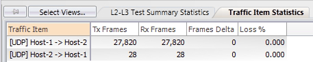
Let’s confirm this by reviewing the statistics for this traffic flow from the traffic generator’s perspective. We don’t see any packet loss:
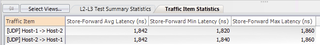
We also see low latency numbers for both traffic flows:
Now that we’ve investigated and resolved this issue, you may have two final lingering questions:
- Why did Host-1 not honor the ICMP Redirect message generated by the switch?
- Why are ICMP Redirects enabled on network devices by default if ICMP Redirects can cause such huge latency and packet loss issues?
I don’t have a great answer for the first question. In my experience, the overwhelming majority of hosts and network devices do not honor or modify their behavior according to incoming ICMP Redirect messages. My suspicion is that this is done for security - in the majority of circumstances, the host’s configured subnet mask takes precedence over incoming ICMP Redirect messages, as ICMP Redirect messages could be spoofed such that legitimate ICMP Redirect messages are indistinguishable from illegitimate ICMP Redirect messages.
With respect to the second question, this behavior is mandated by the IETF through Section 5.2.7.2 of RFC 1812 (Requirements for IP Version 4 Routers):
Routers MUST be able to generate the Redirect for Host message (Code 1) and SHOULD be able to generate the Redirect for Type of Service and Host message (Code 3) specified in [INTERNET:8].
This is what I like to call an “RFC MUST”, which is defined in RFC 2119 (Key words for use in RFCs to Indicate Requirement Levels). As a result, network vendors (Cisco, Juniper, Arista, Dell, HPE, etc.) cannot disable this behavior by default without deviating from an RFC that defines one of the fundamentals of modern-day networking, even if such behavior would be a net positive for the networking world at large. As you can imagine, if one vendor deviated from the RFC, other vendors could have a field day with this by claiming that the first vendor is not RFC compliant with IPv4 networking. From an optics perspective, that looks really bad - after all, if you heard that a specific vendor didn’t fully support basic IPv4 networking in the modern day, your first instinct would probably be to avoid that vendor at all instead of investigating specific details behind this claim!
Ultimately, this issue must be fixed through an IETF RFC that updates RFC 1812 (and the IPv6 equivalent, as I believe the behavior is identical with IPv6 and ICMPv6 Redirect messages).
Conclusion
As demonstrated in this post, it is possible for data plane traffic to become control plane traffic in certain scenarios. Network devices that have some measure of control plane protection will most likely introduce increased latency or packet loss for this data plane traffic. One example scenario has to do with ICMP Redirects, although there exist other scenarios (such as ARP Gleaning) that can introduce a similar issue.