Understanding the Data, Control, and Management Planes of Network Devices
While troubleshooting connectivity issues and packet loss in computer networks, network engineers often misunderstand the difference between the data plane and control plane. This can lead to faulty troubleshooting, as network engineers might attempt to correlate data plane connectivity issues with control plane connectivity issues. In this post, we will investigate the concepts of the data, control, and management plane and explore the differences between them through practical examples.
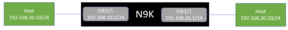
First, let’s take a look at our topology. We have two hosts in different subnets that connect to a Cisco Nexus 9000. One host connects via Ethernet1/1, and the other connects via Ethernet1/2. Ethernet1/1 has an IP of 192.168.10.1, while Ethernet1/2 owns 192.168.20.1.
The architecture of most network devices has three “planes”:
- Data plane
- Control plane
- Management plane
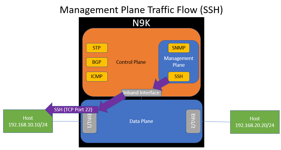
If we expand our view on the internal mechanisms of the Nexus 9000 switch, we can illustrate these three planes as shown here.
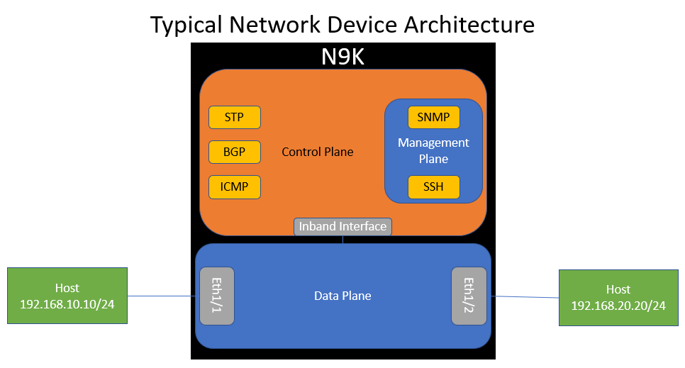
In this image, notice three things:
- The control plane connects to the data plane through an inband interface.
- The control plane hosts various software processes, such as ICMP, BGP, and STP.
- The management plane also hosts various software processes used to manage or monitor the switch (such as SSH and SNMP), and the management plane is contained within the control plane.
Note: In this topology, the management plane is depicted as a sub-section of the control plane. This is a bit of an opinionated view and isn’t necessarily true or factual - however, this is the way I like to visualize the difference between the management plane and the control plane, especially when we consider how features like Control Plane Policing (CoPP) and Hardware Rate Limiters can affect control plane and management plane traffic alike.
Data Plane
The data plane handles traffic going through the network device. This means one of two things:
- For unicast traffic, the destination IPv4 or IPv6 field of traffic entering the device is not set to an IPv4 or IPv6 address assigned to the network device.
- For link-local multicast traffic, the destination IPv4 or IPv6 field of traffic entering the device is not set to an IPv4 or IPv6 address that the network device is listening for.
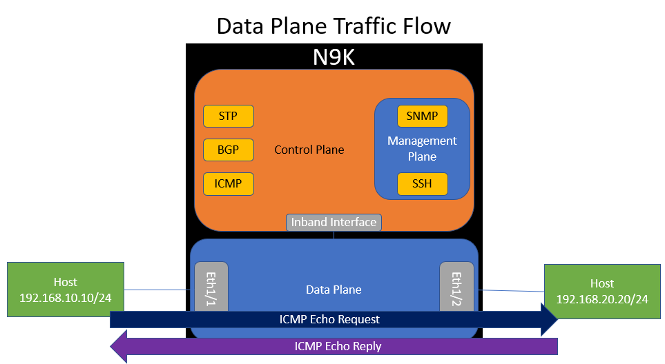
A practical example of data plane traffic in our topology is ICMP traffic between the two hosts. This makes sense, because traffic between the two hosts will go through the switch - it is not destined to the switch.
Control Plane
The control plane handles traffic going to the network device. This means one of two things:
- For unicast traffic, the destination IPv4 or IPv6 field of traffic entering the device is set to an IPv4 or IPv6 address assigned to the network device.
- For link-local multicast traffic, the destination IPv4 or IPv6 field of traffic entering the device is set to an IPv4 or IPv6 address that the network device is listening for.
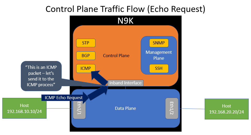
A practical example of control plane traffic in our topology is ICMP traffic destined to the network device itself. If the network device receives an ICMP Echo Request packet destined to an IP address of 192.168.10.1 (which the network device is assigned), the data plane will recognize that the network device itself owns this IP address and forward the packet to the control plane’s inband interface. This action is called a “punt”.
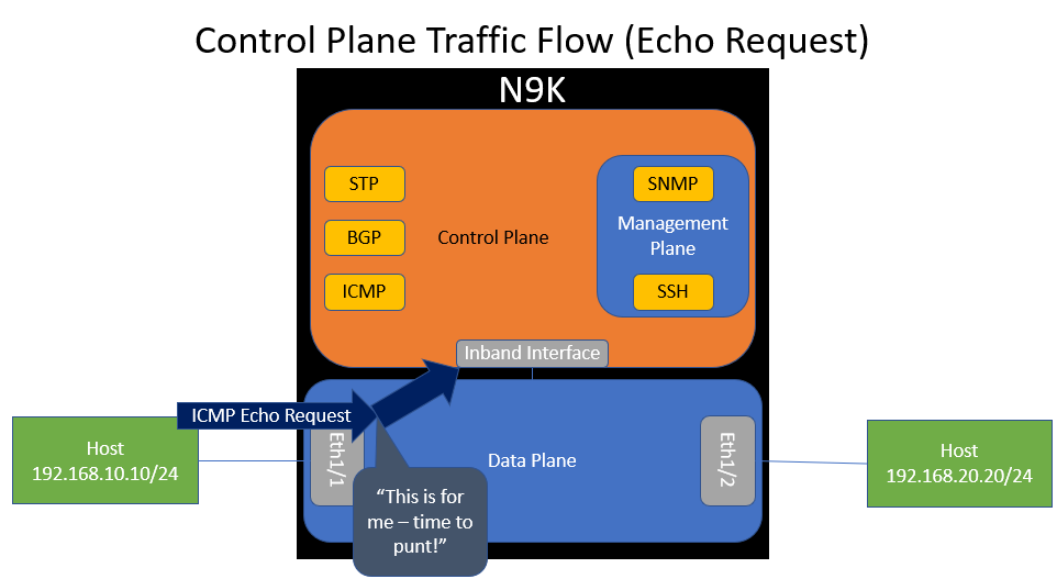
When the control plane receives this ICMP Echo Request packet through the inband interface, it will inspect it and “route” it to the ICMP software process so that the ICMP process can handle it accordingly.
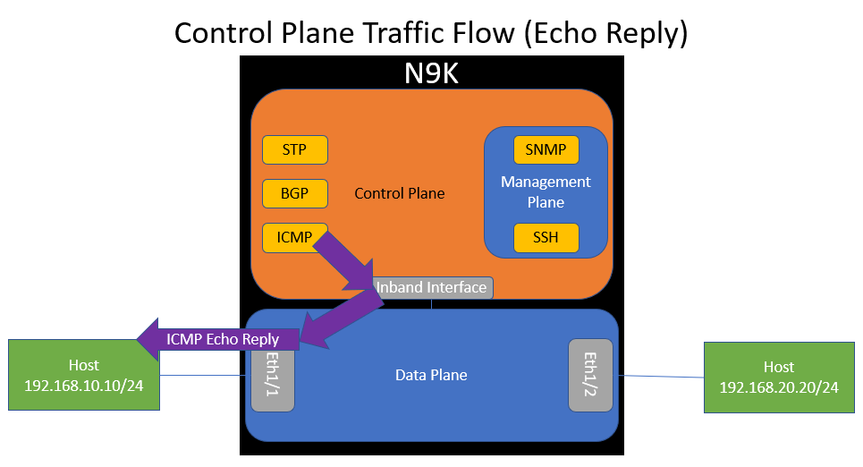
The ICMP software process should generate an ICMP Echo Reply packet, which will be sent to the control plane’s inband interface, which is dequeued by the data plane and forwarded back out of Ethernet1/1 towards the host.
Other common examples of control plane traffic includes routing protocol traffic (such as OSPF, EIGRP, BGP, or PIM packets) and Layer 2 protocols (such as Spanning Tree Protocol, LACP, CDP, or LLDP frames).
Management Plane
The management plane handles traffic going to the network device that is designed to configure, manage, or monitor the network device. Put another way, management plane traffic can be qualified the same way as control plane traffic, but the purpose of the traffic is to configure, manage, or monitor the network device.
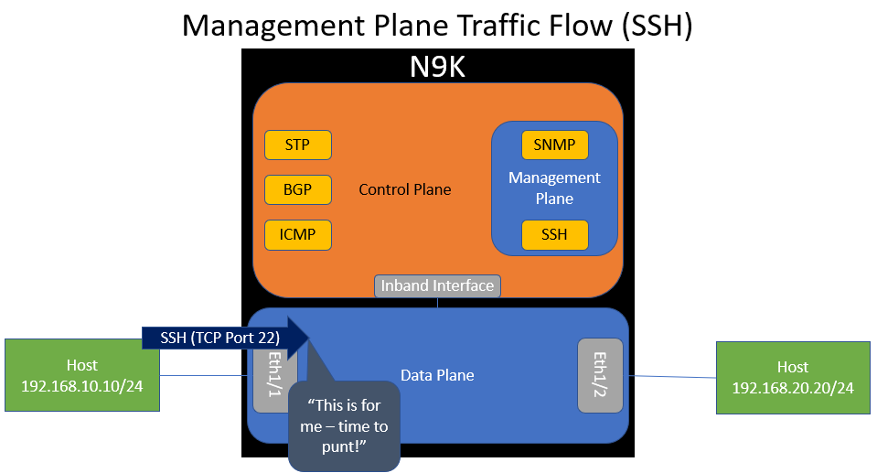
A practical example of management plane traffic in our topology is SSH traffic destined to the network device itself. If the network device receives an ICMP Echo Request packet destined to an IP address of 192.168.10.1 (which the network device is assigned), the data plane will recognize that the network device itself owns this IP address and forward the packet to the control plane’s inband interface. This action is called a “punt”.
When the control plane receives this SSH packet through the inband interface, it will inspect it and “route” it to the SSH software process so that the SSH process can handle it accordingly.
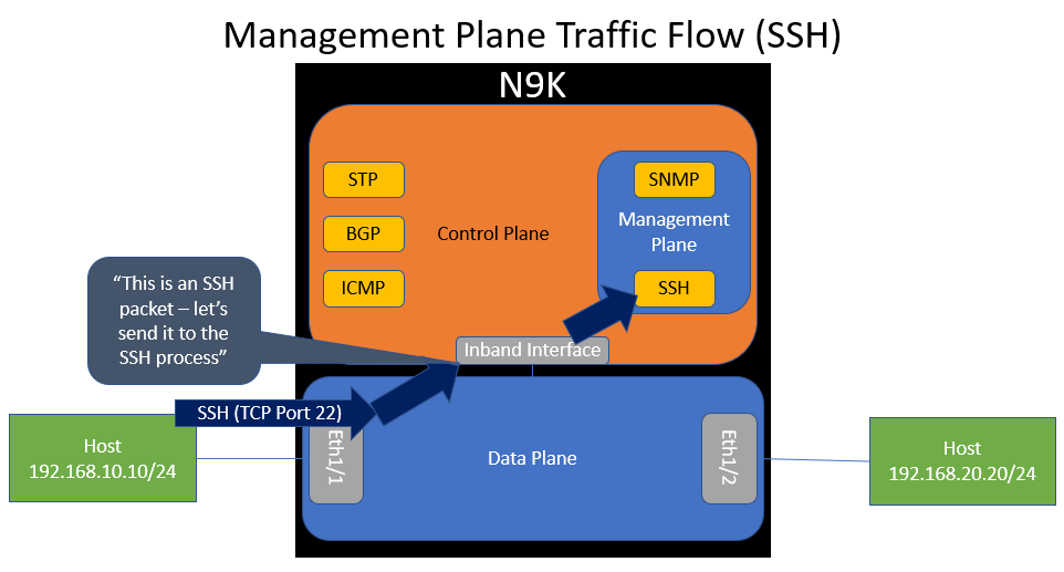
The SSH software process should generate some SSH traffic in reply, which will be sent to the control plane’s inband interface, which is dequeued by the data plane and forwarded back out of Ethernet1/1 towards the host.
Other common examples of management plane traffic includes SNMP traffic (which can be used to monitor the network device as well as configure the device), NETCONF traffic, and gRPC traffic (which can be used to monitor the network device through model-driven telemetry).
Some network devices have a dedicated out-of-band management port that is primarily capable of sending and receiving management plane traffic. Sometimes, this management port can send or receive LLDP or CDP, but rarely do they support other types of control plane protocols (such as Spanning Tree Protocol, routing protocols like OSPF/EIGRP/BGP, etc.)
Control Plane Traffic is Relative
An important concept to keep in mind is that “control plane traffic” is a relative term. A packet can be control plane traffic from the perspective of one device, but data plane traffic from the perspective of another device.
Let’s demonstrate this concept with a practical example. Consider the below topology.
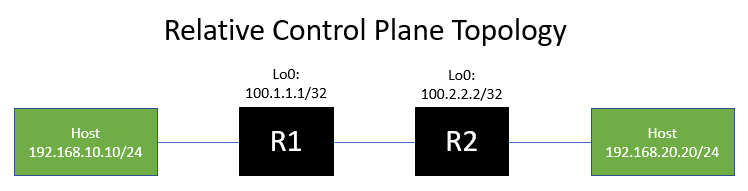
Let’s say an ICMP Echo Request packet is generated by the left-hand host that owns IP address 192.168.10.10. This packet is destined to IP address 100.2.2.2 assigned to R2. When this packet enters R1, R1 will recognize (based on the destination IP address) that the packet need to go through R1, so this ICMP packet will be data plane traffic from R1’s perspective.
However, when this ICMP packet enters R2, R2 will recognize that the destination IP address of the ICMP packet is assigned to R2, which indicates that the packet is for R2. R2 will punt this packet from the data plane to the control plane. Thus, this ICMP packet will be control plane traffic from R2’s perspective.
To summarize - one device’s control plane traffic is another device’s data plane traffic.
This concept is important to keep in mind when troubleshooting issues reported by customers, such as packet loss or connectivity issues. The root cause of data plane packet loss can be different from the root cause of control plane packet loss, or it could be related.
Conclusion
The purpose of this post is to define and illustrate the architectural differences between the data plane, control plane, and management plane of most network devices through practical examples. In future posts, we will demonstrate how these differences can cause unanticipated (but expected!) network device behavior.