Understanding Load Balancing on Network Devices
A common misunderstanding engineers have about Equal-Cost Multi-Pathing (ECMP) and port-channels is that they increase the bandwidth that can be used between two network devices. This can be true, but isn’t always true. In this post, we’ll explore an example scenario where the total bandwidth is not increased as a result of implementing a port-channel, as well as how load-balancing really works on most network devices.
First, let’s get to know our topology. We have three Cisco Nexus switches - Switch-1, Router, and Switch-2 - that are connected in a series. Two traffic generators are connected to Switch-1 and Switch-2 through physical interface Ethernet1/36. Switch-1 and Switch-2 connect to Router through Layer 2 port-channels - port-channel1 connects Switch-1 and Router together, while port-channel2 connects Switch-2 and Router together.
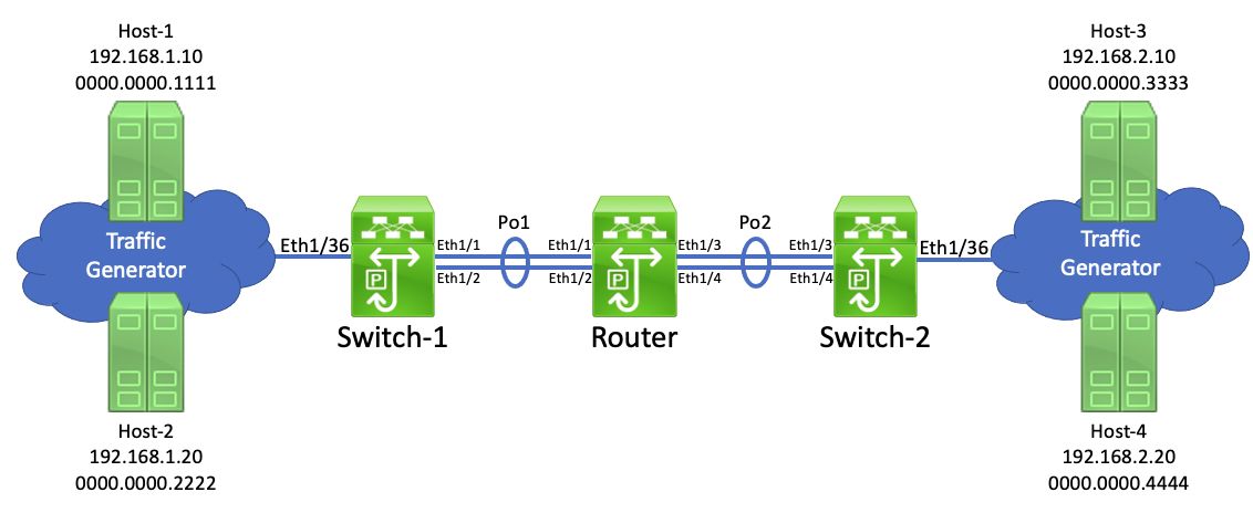
As the names suggest, Switch-1 and Switch-2 are purely Layer 2 switches. Router is a router that routes between two networks - 192.168.1.0/24, and 192.168.2.0/24. The traffic generator mimics four hosts - two in 192.168.1.0/24, two in 192.168.2.0/24.
Let’s say Host-1 (192.168.1.10) sends a packet to Host-3 (192.168.2.10). Switch-1 will inspect the destination MAC address of this packet and know it needs to forward it out of logical interface port-channel1. However, how does Switch-1 know whether to use Ethernet1/1 or Ethernet1/2?
Switch-1 will use a process called hashing to figure out this problem. Hashing is when a network device selects one physical interface out of a group to use when forwarding a specific packet. The method a network device uses to perform hashing is called a hashing algorithm. Hashing algorithms are platform-specific (meaning, they will change depending on the type of switch) and are considered proprietary (meaning, network vendors like Cisco, Juniper, and Arista will never release the hashing algorithm they use in their products to the public.)
One set of inputs for the hashing algorithm is the number of interfaces in the port-channel/ECMP group. Another set of inputs is information about the packet that needs to be forwarded, which we call a flow. Simply put, a flow is a set of attributes that uniquely identify one packet from other packets. To use the same terms defined by Cisco’s NetFlow protocol, each attribute is called a field. Each network device in the path of a particular set of traffic can define a flow differently using a tuple of fields called key fields.
In other words, one device may say that a unique flow consists of the source and destination MAC address key fields, while another device may say that a unique flow consists of the source and destination MAC address and IP address key fields.
For a practical example of this concept, let’s two ICMP Echo Request packets - one sent from Host-1 to Host-3, and another sent from Host-1 to Host-4. If we were to capture these packets as they enter Switch-1, their headers would look like this.
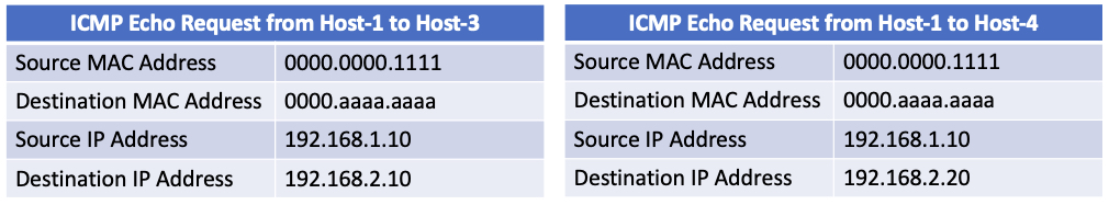
As you can see, the only difference between these two sets of packets is the destination IP address. However, if Switch-1 considers only the source and destination MAC address fields to be key fields, then SWITCH-1 would consider both traffic patterns to be identical flows, even though they’re destined to two different IP addresses.
Most network devices have a command that let’s you see what key fields it considers in its hashing algorithm. On NX-OS, this command is show port-channel load-balance. On Cisco IOS, this command is show etherchannel load-balance.

Note that even though Switch-1 is a Layer 2 switch, its Application-Specific Integrated Circuit (ASIC) is perfectly capable of parsing Layer 3 and Layer 4 headers of incoming packets in addition to Layer 2 headers. Just because Switch-1 is a Layer 2 switch doesn’t mean it isn’t able to read/understand IP addresses and TCP/UDP headers - it just means it won’t make forwarding decisions based on Layer 3 or Layer 4 headers. However, Switch-1 will factor this data into its hashing algorithm.
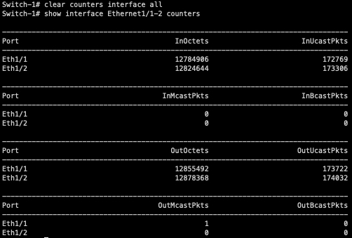
In our topology, both Host-1 and Host-2 are continuously sending traffic to both Host-3 and Host-4 in a full-mesh fashion. We can use interface counters on Switch-1 to see how traffic is hashing on Switch-1.
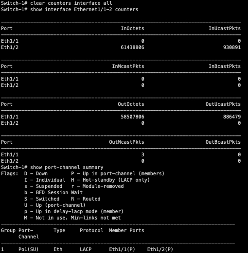
As you can see, all traffic is traversing Ethernet1/1 of Switch-1. Ethernet1/2 is completely unused, even though it’s up/up and bundled within port-channel1.
What’s going on here? Is this a bug? Do I refund my expensive data center switches, since they’re clearly broken?
Nope! This is 100% expected behavior. Simply put, we’re getting “lucky” (or unlucky, depending on your perspective) with the hashing algorithm. All of our traffic happens to hash to the same physical interface within the bundle - an event we like to call “polarization”.
This means that even though two 10Gbps interfaces are bundled together, you may not get 20Gbps of bandwidth out of the bundle. If the majority of your flows (or at least your high-bandwidth flows) hash to one member of the port-channel, you’re still oversubscribed.
In my scenario, the packets generated by the traffic generator do not have a Layer 4 header.
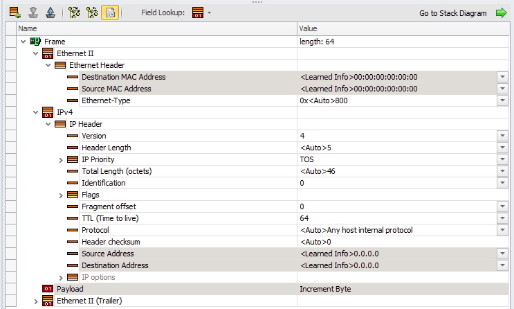
Since Switch-1’s hashing algorithm can use Layer 3 and Layer 4 headers, let’s add a UDP header with randomized ports to add some entropy to our traffic flow.

Now that we have a Layer 4 header to work with, we can see the traffic is very nicely load-balanced across Ethernet1/1 and Ethernet1/2! With this traffic pattern, we should be able to squeeze 20Gbps of bandwidth out of this port-channel.
Next, you may want to know exactly how hashing works. As stated before, the exact hashing algorithm used by a switch is proprietary information. However, at a high level, the switch will do some quick math on the relevant headers of the packet (selected based upon the port-channel’s load-balancing algorithm) and the algorithm will spit out an integer number. Let’s say the number the algorithm spits out is between 0 and 7.
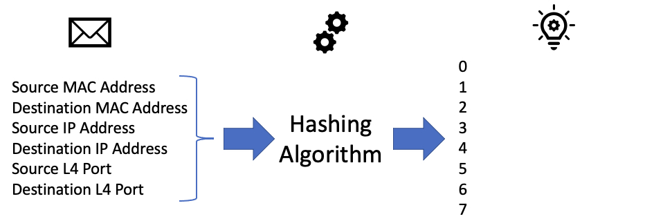
Internally, the network device will assign each physical interface in the port-channel or ECMP group a number. In our example, Ethernet1/1 may be internally assigned 0, 1, 2, and 3. Ethernet1/2 may be internally assigned 4, 5, 6, and 7.

If the number spit out by the algorithm is 0, 1, 2, or 3, then the switch will forward the packet out of Ethernet1/1. If the number spit out by the algorithm is 4, 5, 6, or 7, then the switch will forward the packet out of Ethernet1/2.
In the case of unequal-cost multipathing (also called “unequal-cost load balancing” by some technologies, such as EIGRP), you will have two paths. Path 1 might have a poorer metric, so internally it’ll be given hashes 0 and 1. Path 2 might have a better metric, so internally it’ll be given hashes 2, 3, 4, 5, 6, and 7. If the number spit out by the algorithm when run against a flow is 0 or 1, then Path 1 will be taken. If the number spit out by the algorithm when run against a flow is 2, 3, 4, 5, 6, or 7, then Path 2 will be taken.
This algorithm is not aware of the amount of traffic that belongs to a flow. The flow could be a few kilobits per second, which would probably be fine to flow down Path 1. It could also be several gigabits per second, which could cause congestion further down the path. The router doesn’t keep track of how much traffic is present in a flow (or at least, if it does via sFlow or NetFlow, the data gathered by that technology does not impact the router’s forwarding decision made on that packet/flow).
In our example, the integer number that our algorithm returns is between 0 and 7, which is a total of 8 values. Each individual integer is sometimes called a bit bucket, which means the platform in our example supports a total of 8 bit buckets. On older networking platforms, vendors recommend that when you use ECMP or port-channels, you have a number of interfaces equal to some power of two (such as 2, 4, 8, 16, etc.) within the ECMP or port-channel. Using some other number (such as 3, 6, etc.) will result in one or more interfaces being internally assigned less hash values than other interfaces on older networking platforms, resulting in unequal-cost load balancing.
Modern networking platforms often have a significantly higher number of bit buckets. The exact number varies and is rarely advertised, but 32, 64, 128, and even 256 bit buckets are possible. Therefore, these platforms are less susceptible to unequal-cost load balancing in scenarios where an ECMP or port-channel does not have a number of interfaces equal to a power of two.