Understanding Control Plane Packet Loss due to CoPP
Note: If you are not familiar with the concepts of the data plane and control plane on network devices, I highly recommend reviewing my Understanding the Data, Control, and Management Planes of Network Devices post prior to reading this post.
Network engineers often have to troubleshoot packet loss or connectivity issues across the network between hosts reported by customers. As part of troubleshooting this issue, network engineers often use ping to send ICMP Echo Request to various devices in the network, including intermediary network devices like switches and routers. During this troubleshooting, they may observe packet loss while pinging a network device and assume that it is related to the issue they are troubleshooting. In reality, this packet loss is not related to their issue and is expected behavior.
In this post, we will dive into this behavior in more detail to explain why control plane packet loss such as this can be expected behavior and not necessarily indicative of an issue with the network device.
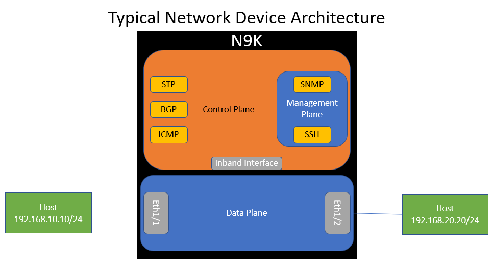
First, let’s take a look at our topology. We have two hosts in different subnets that connect to a Cisco Nexus 9000 switch. One host connects via Ethernet1/1, and the other connects via Ethernet1/2. Ethernet1/1 has an IP of 192.168.10.1, while Ethernet1/2 owns 192.168.20.1.
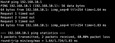
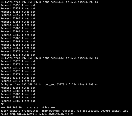
Let’s presume that you are troubleshooting a connectivity issue between both hosts in this topology. While troubleshooting, you perform a ping from the left-hand host owning 192.168.10.10 to the Nexus 9000 switch owning 192.168.10.1 and see packet loss similar to the below:
As described in a previous blog post, the architecture of most network devices has three “planes” - a data plane, a control plane, and a management plane. This control plane packet loss scenario focuses on the interaction between the data plane and the control plane. Recall that the data plane handles traffic going through the device, while the control plane handles traffic going to the device.
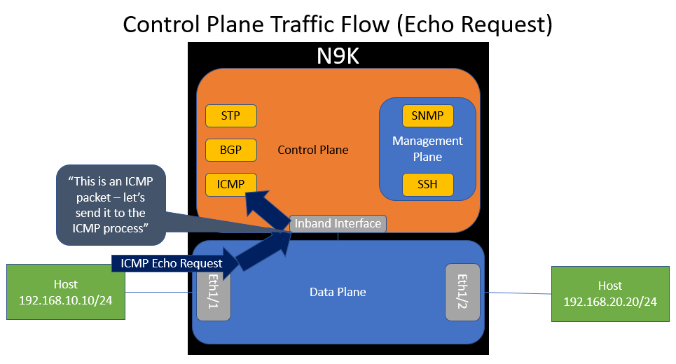
If we visualize the data plane and control plane of our switch within our topology, it would look like the diagram below. Notice how the control plane connects to the data plane through an inband interface. Also notice how the control plane hosts various software processes, such as ICMP.
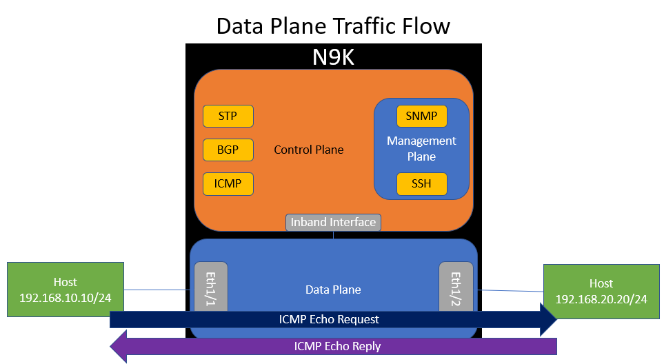
ICMP traffic between the two hosts flows through the data plane of the switch. This makes sense, because traffic between the two hosts will go through the switch - it is not destined to the switch.
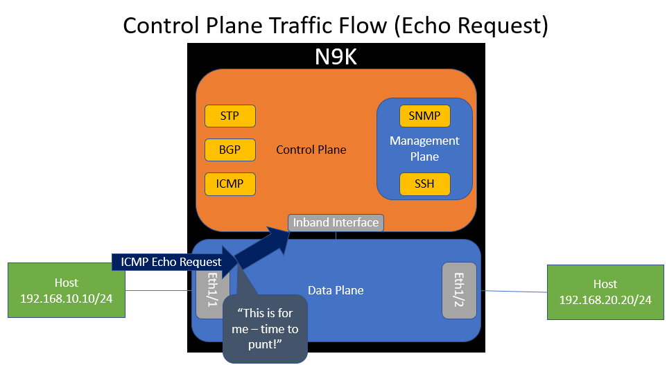
However, what if the switch gets an ICMP Echo Request packet destined to itself (e.g. 192.168.10.1)? The data plane will recognize that the switch itself owns IP 192.168.10.1 and forward the packet to the control plane’s inband interface. This action is called a “punt”.
When the control plane receives this packet through the inband interface, it will inspect it and “route” it to the ICMP software process so that the ICMP process can handle it accordingly.
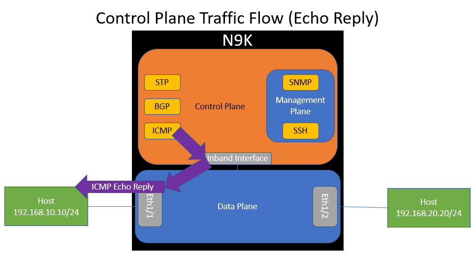
The ICMP software process should generate an ICMP Echo Reply packet, which will be sent to the control plane’s inband interface, which is dequeued by the data plane and forwarded back out of Ethernet1/1 towards the host.
However, what if the switch was receiving a lot of ICMP traffic all at once? For example, a malicious actor may be sending the switch more ICMP traffic than it can handle, or maybe a network monitoring system (NMS) is aggressively monitoring switch reachability through ICMP. This could clog the inband interface and control plane with unnecessary traffic or cause high CPU utilization, which would inadvertently affect other control plane protocols (such as BGP, OSPF, Spanning Tree Protocol, etc.) and cause instability in the network.
This is where the concept of “Control Plane Protection” comes in. We need a mechanism to rate limit the amount of control plane traffic sent to a network device so that the control plane of the network device does not get overwhelmed with traffic. On Cisco Nexus switches, Control Plane Protection is primarily implemented through “Control Plane Policing” - a feature better known by its acronym, CoPP. This is enabled by default, but you can confirm it’s configured with the show copp status command, as shown below.
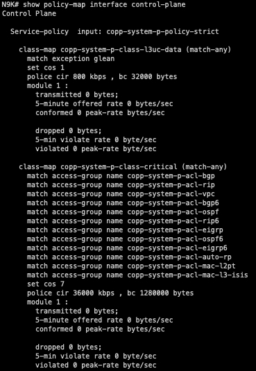
CoPP is implemented within the data plane of the switch and enables the data plane to drop a specific class of traffic if the rate of traffic for that class exceeds a threshold. It’s essentially a QoS (Quality of Service) policer for the control plane. The output of the show policy-map interface control-plane command can show us how classes in the CoPP policy are organized, what type of traffic corresponds with each class, and each class’s policer rate.
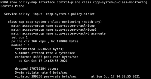
In our scenario, the “copp-system-p-class-monitoring” CoPP class handles ICMP traffic. We can see that by default, a 360 kbps CIR (Committed Information Rate) of ICMP traffic is allowed with a 128 kilobyte Bc (committed burst).
We can also see that 32 megabytes of ICMP traffic has been allowed by this CoPP class, while about 279 megabytes of ICMP traffic has been dropped by this CoPP class since the last time the counters were cleared. Clearly, this switch is being blasted with ICMP traffic!
As it turns out, I had another SSH session open to my host that was mindlessly slamming the Nexus with ICMP traffic. Oops!
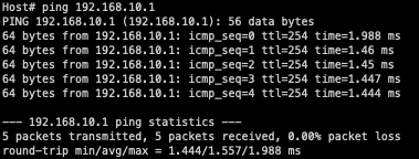
Now that I’ve stopped the other ping command, we can see that my original ping works as expected with no packet loss.
This means that the packet loss observed while pinging the Nexus 9000 switch is not related to the connectivity issues between the two hosts in this network. The packet loss observed while pinging the Nexus 9000 switch was control plane traffic and was being dropped due to CoPP, while the connectivity issue between the two hosts involves data plane traffic and has a separate root cause.
Conclusion
The moral of this story is that there is a fundamental difference between data plane traffic and control plane traffic. When you become aware of a connectivity or packet loss issue in your network, your first instinct will be to test connectivity between various points of your network. If this issue involves data plane traffic, make sure that your test traffic is also data plane traffic and not control plane traffic. Otherwise, your test traffic and your problematic traffic will yield fundamentally different results that could mislead your troubleshooting efforts..
Similarly, when deploying a portion of your network for the first time, the proper way to validate that the network is working correctly is by testing with data plane traffic (e.g. ICMP pings between two hosts/endpoints connected to the network) instead of control plane traffic (e.g. ICMP pings between a host and the host’s default gateway). This doesn’t mean that every time you deploy a new network, you need to get access to a bunch of hosts to properly test connectivity - you can certainly still test basic connectivity using control plane traffic. However, if you see issues (especially packet loss) with your control plane traffic, you need to validate whether the issues are due to the network by testing with data plane traffic.

