Understanding ARP Glean
Note: If you are not familiar with the concepts of the data plane and control plane on network devices, I highly recommend reviewing my Understanding the Data, Control, and Management Planes of Network Devices post prior to reading this post.
In a previous blog post, we investigated one scenario that explains why the first packet of a ping command is lost.
1
2
3
4
5
6
Router#ping 192.0.2.130

Type escape sequence to abort.
Sending 5, 100-byte ICMP Echos to 192.0.2.130, timeout is 2 seconds:
.!!!!
Success rate is 80 percent (4/5), round-trip min/avg/max = 1/1/3 ms
The scenario investigated by the previous blog post was a simple topology where a router is attempting to ping a directly connected host. However, this is not the only scenario where this issue may happen. In production environments, this issue is commonly seen when a source attempts to ping a destination, but:
- An intermediary router does not have the Media Access Control (MAC) address resolved via Address Resolution Protocol (ARP) for the next hop towards the ping packet’s destination IP address.
- The last hop router does not have ARP resolved for the ping packet’s destination IP address itself if the device has a directly connected route in its routing table.
In either of these scenarios, the data plane of the relevant router must internally transfer the ping packet to the control plane of the router (an action commonly called a punt) in order to generate an ARP Request packet for either the next hop IP address or the destination IP address. The punted ping packet is dropped by the control plane, thus causing the initial packet loss. This type of punt is commonly referred to as “ARP Glean”.
Note: “Glean” is a Cisco-centric term that will be used throughout this article. Some vendors (such as Arista) use this term, while other vendors (Juniper, Nvidia, Dell, HPE, etc.) do not.
In this article, we will illustrate how ARP Glean occurs step-by-step by focusing on a simple topology involving the latter of the aforementioned scenarios where the last hop router does not have ARP resolved for the ping packet’s destination IP address.
Topology
First, let’s review the topology we will use in this article.
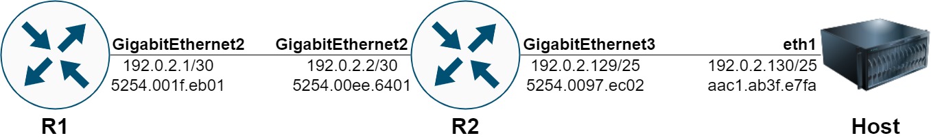
This topology involves three devices - two Cisco Catalyst 8000v virtual routers running Cisco IOS-XE 17.08.01a, and a Linux host named “Host” running the Ubuntu 20.04 operating system. The first Catalyst 8000v virtual router is named “R1”, and its GigabitEthernet2 interface is assigned IPv4 address 192.0.2.1/30. R1’s GigabitEthernet2 interface connects to GigabitEthernet2 of the second Catalyst 8000v virtual router, which is named “R2”. R2’s GigabitEthernet2 interface is assigned IPv4 address 192.0.2.2/30. R2’s GigabitEthernet3 interface is assigned an IPv4 address of 192.0.2.129/25 is directly connected to Host’s eth1 interface with an IPv4 address of 192.0.2.130/25.
R1 and R2 are both running the Open Shortest Path First (OSPF) dynamic unicast routing protocol. R1’s GigabitEthernet2 interface is activated under R1’s OSPF process, while R2’s GigabitEthernet2 and GigabitEthernet3 interfaces are activated under R2’s OSPF process. As a result, R1 has an OSPF-learned route for 192.0.2.128/25 in its unicast routing table.
1
2
3
4
5
6
7
8
9
R1#show ip route
<snip>
Codes: L - local, C - connected, S - static, R - RIP, M - mobile, B - BGP
       D - EIGRP, EX - EIGRP external, O - OSPF, IA - OSPF inter area

      192.0.2.0/24 is variably subnetted, 3 subnets, 3 masks
C        192.0.2.0/30 is directly connected, GigabitEthernet2
L        192.0.2.1/32 is directly connected, GigabitEthernet2
O        192.0.2.128/25 [110/2] via 192.0.2.2, 00:08:30, GigabitEthernet2
Processing the First Ping
As you can see below, when the ping 192.0.2.130 command is executed on the R1 router, the first packet is lost.
1
2
3
4
5
R1#ping 192.0.2.130
Type escape sequence to abort.
Sending 5, 100-byte ICMP Echos to 192.0.2.130, timeout is 2 seconds:
.!!!!
Success rate is 80 percent (4/5), round-trip min/avg/max = 1/2/4 ms
Let’s walk through precisely what happens when the ping 192.0.2.130 command is executed on the R1 router.
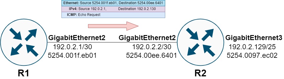
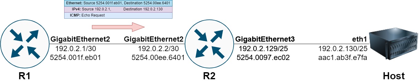
The management and control planes of the R1 router will generate an ICMP Echo Request packet. This packet will be sent out of R1’s GigabitEthernet2 interface towards R2’s GigabitEthernet 2 interface.
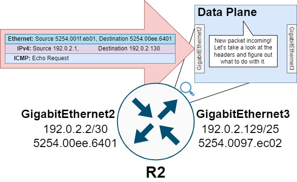
When the ICMP Echo Request packet ingresses R2, R2’s data plane will analyze the packet and attempt to make a forwarding decision on it.
First, R2 will references its routing table for the destination IP address 192.0.2.130. In our scenario, the longest prefix match for this IP address is the 192.0.2.128/25 route directly connected to interface GigabitEthernet3.
1
2
3
4
5
6
R2#show ip route 192.0.2.130
Routing entry for 192.0.2.128/25
  Known via "connected", distance 0, metric 0 (connected, via interface)
  Routing Descriptor Blocks:
  * directly connected, via GigabitEthernet3
      Route metric is 0, traffic share count is 1
The data plane of routers running Cisco IOS or IOS-XE will use the Cisco Express Forwarding (CEF) feature to accelerate this lookup. The output of show ip cef below confirms that the 192.0.2.128/25 route is directly connected to interface GigabitEthernet3.
1
2
3
R2#show ip cef 192.0.2.130
192.0.2.128/25
  attached to GigabitEthernet3
Next, R2 will need to rewrite the Ethernet header of the ICMP Echo Request packet. Specifically, it needs to determine the source and destination MAC address that will be populated in the Ethernet header. The source MAC address will be the MAC address assigned to R2’s GigabitEthernet3 interface (5254.0097.ec02) that the packet will egress from. The destination MAC address should be the MAC address assigned to Host’s eth1 interface, which is aac1.ab3f.e7fa as shown through the output of the ip link show eth command.
1
2
3
root@Host:/# ip link show eth1
29: eth1@if30: <BROADCAST,MULTICAST,UP,LOWER_UP> mtu 9500 qdisc noqueue state UP mode DEFAULT group default
    link/ether aa:c1:ab:3f:e7:fa brd ff:ff:ff:ff:ff:ff link-netnsid 1
R2 needs to resolve Host’s MAC address using Host’s IPv4 address 192.0.2.130. The router will do this using the Address Resolution Protocol (ARP). The router will consult its ARP cache, looking for an existing entry for 192.0.2.130. The output of the show ip arp 192.0.2.130 command below is empty, suggesting that no such entry exists. This is confirmed with the full output of the show ip arp command.
1
2
3
4
5
6
R2#show ip arp
Protocol  Address          Age (min)  Hardware Addr   Type   Interface
Internet  192.0.2.1             146   5254.001f.eb01  ARPA   GigabitEthernet2
Internet  192.0.2.2               -   5254.00ee.6401  ARPA   GigabitEthernet2
Internet  192.0.2.129             -   5254.0097.ec02  ARPA   GigabitEthernet3
R2#
R2 cannot proceed with forwarding this ICMP Echo Request packet out of its GigabitEthernet3 interface without first resolving the MAC address associated with the host assigned 192.0.2.130. R2 needs to resolve this MAC address by generating an ARP Request targeting any host assigned an IPv4 address of 192.0.2.130.
However, the data plane of network devices is generally not responsible for or capable of creating new packets. The data plane can modify existing packets by rewriting fields of headers, encapsulating packets with new headers, but creating a new packet from scratch is outside of its realm of specialty. On the other hand, the control plane of network devices is more than capable of creating a new packet from scratch.
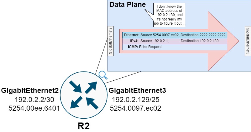
Therefore, the data plane needs to transfer this ICMP Echo Request packet to the control plane for further processing (an action commonly called a punt). Specifically, R2’s data plane will punt this ICMP Echo Request packet to the control plane using a “glean” adjacency, as shown by the output of show ip cef 192.0.2.130 internal below.
1
2
3
4
5
6
7
8
9
10
11
12
13
14
15
16
R2#show ip cef 192.0.2.130 internal
192.0.2.128/25, epoch 2, flags [att, cnn, cover, deagg], RIB[C], refcnt 6, per-destination sharing
  sources: RIB
  feature space:
    Broker: linked, distributed at 2nd priority
  subblocks:
    gsb Connected chain head(1): 0x7F91D4805BD8
    Covered dependent prefixes: 2
      need deagg: 2
  ifnums:
    GigabitEthernet3(7)
  path list 7F91D4628510, 3 locks, per-destination, flags 0x49 [shble, rif, hwcn]
    path 7F91D4629468, share 1/1, type connected prefix, for IPv4
      connected to GigabitEthernet3, glean    <<<
  output chain:
    glean    <<<
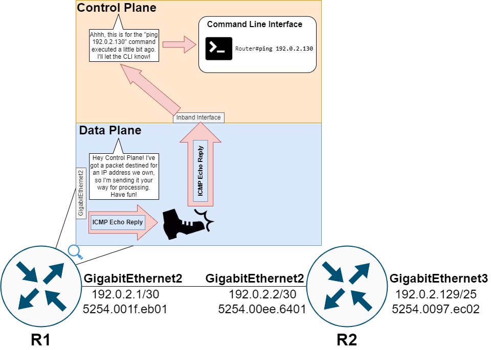
The punt from R2’s data plane to R2’s control plane for ARP Glean is illustrated below.
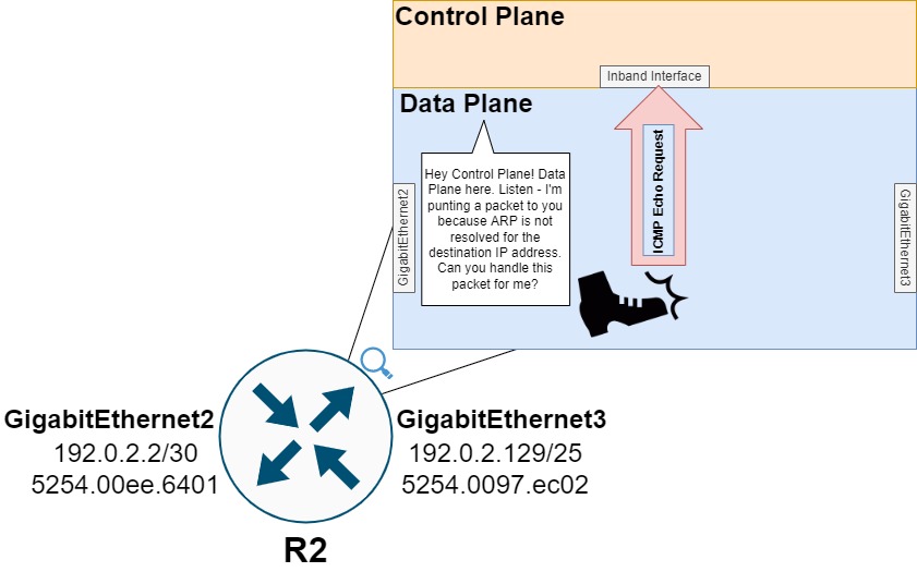
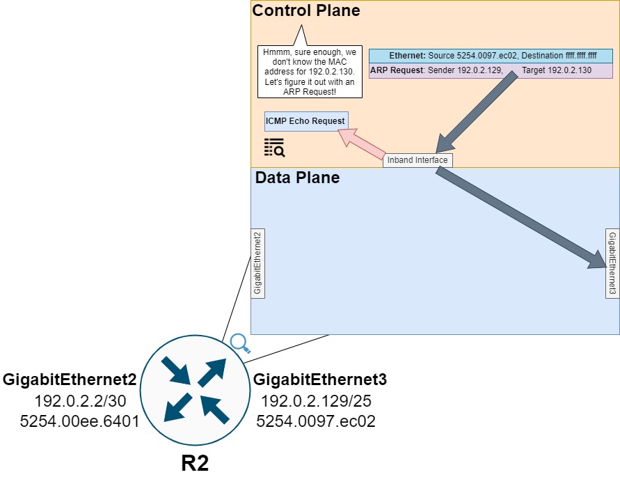
The control plane will receive this ICMP Echo Request packet and understand that an ARP Request is needed to resolve the MAC address for 192.0.2.130.
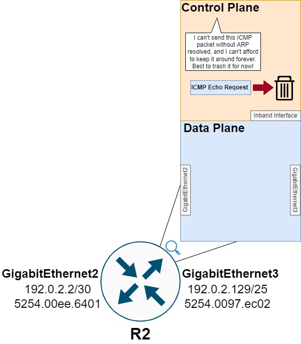
The control plane will then drop the ICMP Echo Request packet. This drop explains why the first ping in R1’s ping command fails, as the ICMP Echo Request packet never egresses R2’s GigabitEthernet3 interface towards Host.
Note: A few reasons behind why this ICMP Echo Request packet is dropped by the control plane is explained in the “Why Is The First Packet Dropped?” section of the Illustrating Why the First ICMP Ping is Lost blog post.
To populate the ARP cache with a valid entry, the router will broadcast an ARP Request frame to all hosts on the 192.0.2.128/25 subnet asking for the host assigned the 192.0.2.130 IP address to respond with the host’s MAC address.
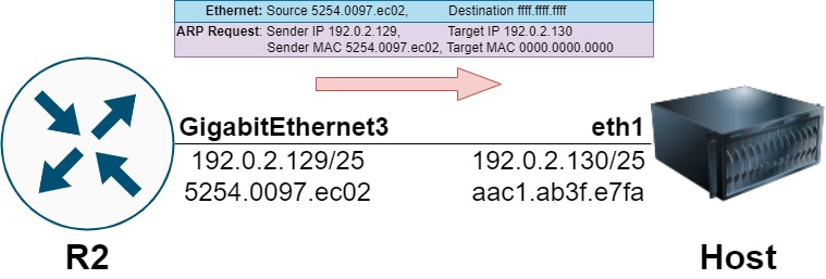
The host will respond with a unicast ARP Reply frame informing the router that the host’s MAC address is aac1.ab3f.e7fa.
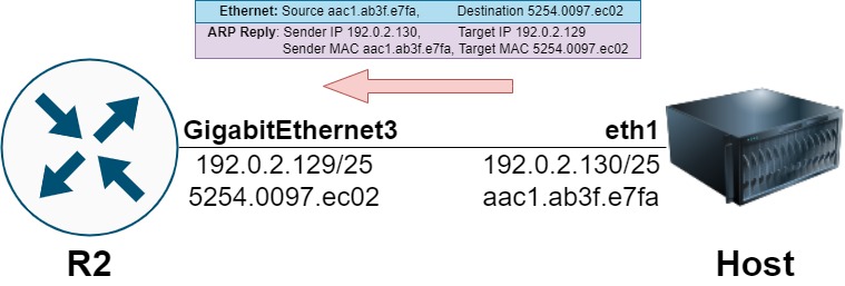
This procedure is demonstrated through the packet capture on the host below.
1
2
3
4
root@Host:/# tcpdump -i eth1 -vvvv
tcpdump: listening on eth1, link-type EN10MB (Ethernet), capture size 262144 bytes
19:41:40.969329 ARP, Ethernet (len 6), IPv4 (len 4), Request who-has 192.0.2.130 tell 192.0.2.129, length 46
19:41:40.969345 ARP, Ethernet (len 6), IPv4 (len 4), Reply 192.0.2.130 is-at aa:c1:ab:3f:e7:fa (oui Unknown), length 28
The router’s ARP cache will now have an entry for 192.0.2.130, as demonstrated through the output of show ip arp 192.0.2.130 below.
1
2
3
R2#show ip arp 192.0.2.130
Protocol  Address          Age (min)  Hardware Addr   Type   Interface
Internet  192.0.2.130            15   aac1.ab3f.e7fa  ARPA   GigabitEthernet3
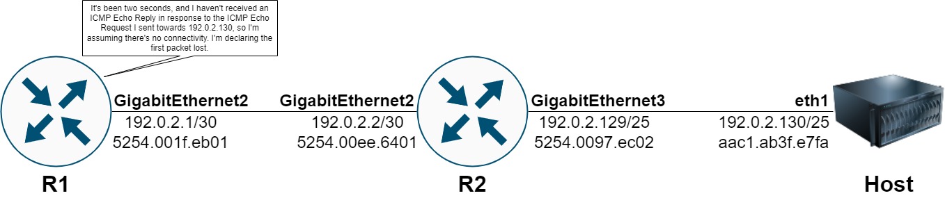
Recall that the original ICMP Echo Request packet created by R1 was dropped by R2’s control plane. R1 has no knowledge of R2’s ARP table, whether it is populated with a valid entry for 192.0.2.30, and the ultimate fate of the ICMP Echo Request packet. R1 simply expects to receive an ICMP Echo Reply packet in response to the ICMP Echo Request packet it created within the defined timeout period (default 2 seconds in Cisco IOS-XE). When this timeout period expires, R1 will mark that instance of the ping unsuccessful.
At this brief moment in time, the command line output for the ping 192.0.2.130 command will look like the following.
1
2
3
4
R1#ping 192.0.2.130
Type escape sequence to abort.
Sending 5, 100-byte ICMP Echos to 192.0.2.130, timeout is 2 seconds:
.
Processing the Second Ping
The ping 192.0.2.130 command executed on R1 will repeat the above process with a second ICMP Echo Request packet when the timeout period for the first ICMP Echo Request packet expires.
When this ICMP Echo Request packet ingresses R2, R2’s data plane will analyze the packet to make a forwarding decision. Now that ARP is resolved for 192.0.2.130 on R2, the output of show ip cef 192.0.2.130 shows a new 192.0.2.130/32 entry in the data plane forwarding table. This entry has a pointer to the adjacency table at 0x7F91D48050F0 .
1
2
3
4
5
6
7
8
9
R2#show ip cef 192.0.2.130
192.0.2.130/32
  attached to GigabitEthernet3

R2#show ip cef 192.0.2.130 detail
192.0.2.130/32, epoch 2, flags [attached]
  Adj source: IP adj out of GigabitEthernet3, addr 192.0.2.130 7F91D48050F0
    Dependent covered prefix type adjfib, cover 192.0.2.128/25
  attached to GigabitEthernet3
The data plane adjacency table’s entry for 192.0.2.130 confirms that the pointer is pointing to the correct entry. We can also see the post-routed Ethernet header for this adjacency, which has:
- The destination MAC address for the adjacency, AAC1AB3FE7FA (aac1.ab3f.e7fa)
- The source MAC address for the adjacency, 52540097EC02 (5254.0097.ec02)
- An Ethertype value (0800) indicating that the next protocol in the stack is IPv4
1
2
3
4
5
6
7
8
9
10
11
12
13
14
15
16
17
18
19
20
21
22
23
R2#show adjacency 192.0.2.130 internal
Protocol Interface                 Address
IP       GigabitEthernet3          192.0.2.130(8)
                                   9 packets, 1026 bytes
                                   epoch 0
                                   sourced in sev-epoch 8
                                   Encap length 14
                                   AAC1AB3FE7FA52540097EC020800    <<<
                                   L2 destination address byte offset 0
                                   L2 destination address byte length 6
                                   Link-type after encap: ip
                                   ARP
                                   Fast adjacency enabled [OK]
                                   L3 mtu 1500
                                   Flags (0x1088E)
                                   Fixup disabled
                                   HWIDB/IDB pointers 0x7F91D157EC38/0x7F916681DA20
                                   IP redirect disabled
                                   Switching vector: IPv4 no fixup adj oce
                                   Platform adj-id: 0x22, 0x0, tun_qos_dpidx:0

                                   Adjacency pointer 0x7F91D48050F0    <<<
                                   Next-hop 192.0.2.130
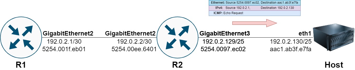
This information enables the data plane to forward this packet out of GigabitEthernet3 without needing to punt the packet to the control plane for additional processing. The ICMP Echo Request packet egresses out of GigabitEthernet3 towards Host.
Host responds with an ICMP Echo Reply packet destined to R1’s 192.0.2.1.
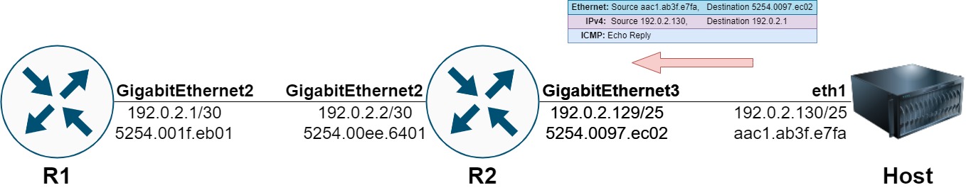
R2’s data plane routes this packet towards R1, rewriting the Ethernet headers accordingly.

R1 receives the ICMP Echo Reply packet from Host, which is punted by R1’s data plane to the control plane because R1 owns the IPv4 address that the ICMP Echo Reply is destined to.
At this brief moment in time, the command line output for the ping 192.0.2.130 command will look similar to the following.
1
2
3
4
R1#ping 192.0.2.130
Type escape sequence to abort.
Sending 5, 100-byte ICMP Echos to 192.0.2.130, timeout is 2 seconds:
.!
This procedure will repeat three more times, with ICMP Echo Request packets being generated by R1, forwarded by the data plane of R2 towards Host, ICMP Echo Reply packets generated in response by Host, forwarded by the data plane of R2 towards R1, and R1’s control plane receiving the ICMP Echo Reply from Host. At the conclusion of this transaction, the command line output for the ping 192.0.2.130 command will look similar to the following.
1
2
3
4
5
R1#ping 192.0.2.130
Type escape sequence to abort.
Sending 5, 100-byte ICMP Echos to 192.0.2.130, timeout is 2 seconds:
.!!!!
Success rate is 100 percent (5/5), round-trip min/avg/max = 1/6/16 ms
Conclusion
In summary, most network operating systems will punt a packet from the device’s data plane to the control plane if ARP is not resolved for either:
- The next hop towards the packet’s destination IP address.
- The destination IP address itself, if the device has a directly connected route in its routing table.
There are many reasons why the data plane may punt a packet to the control plane, and this specific reason is typically called “ARP Glean”. The control plane uses the punted packet to generate an ARP Request for the next hop IP address or the destination IP address. The punted packet is then dropped, which causes the first packet in the traffic flow to be lost.
This behavior is typically observed when you are sending traffic to an IP address for the first time (such as if a new host has been recently connected to the network). Once ARP is resolved, subsequent packets in the traffic flow will be forwarded by the data plane of the device as expected.
This behavior has been seen on the following network operating systems:
- Cisco IOS
- Cisco IOS-XE
- Cisco NX-OS