Quick Lab - RIPv2 Auto Summary
RIPv2’s automatic network summarization feature is easy to misunderstand, which can be a recipe for disaster in a production environment or on the CCIE R&S lab exam. Let’s analyze the exact behavior behind this feature by experimenting with it in a quick lab!
Scope
In this lab, we seek answers to the following question:
What scenario(s) will cause RIPv2 automatically summarize networks?
What is a classful network boundary, and why does RIPv2 summarize around them?
Topology

Lab Materials
This lab was completed with a VIRL 1.6.65 server using the IOSv 15.7(3)M3 node.
Default Configuration
Both nodes are configured with their hostname, RIPv2 that advertises all up/up interfaces with Auto-Summary enabled, and other utility configuration by default. R1’s default configuration includes configuration for the Gi0/1 interface and five loopback interfaces, as shown below. Note that the loopback interfaces are explicitly configured as passive interfaces - this is to ensure RIPv2 debug output later in the lab is clean, as otherwise RIPv2 will attempt to send update messages out of each loopback interface every 30 seconds.
1
2
3
4
5
6
7
8
9
10
11
12
13
14
15
16
17
18
19
20
21
22
23
24
25
26
27
28
29
30
31
32
33
34
35
36
37
38
39
40
41
42
43
44
45
46
47
hostname R1
no ip domain-lookup
service timestamps debug datetime msec
service timestamps log datetime msec
logging buffered 10000000

interface GigabitEthernet0/0
  shutdown

interface GigabitEthernet0/1
  no shutdown
  ip address 10.0.0.1 255.255.255.252

interface Loopback0
  no shutdown
  ip address 192.168.1.1 255.255.255.0

interface Loopback1
  no shutdown
  ip address 192.168.2.1 255.255.255.128

interface Loopback2
  no shutdown
  ip address 192.168.2.129 255.255.255.128

interface Loopback3
  no shutdown
  ip address 10.0.10.1 255.255.254.0

interface Loopback4
  no shutdown
  ip address 10.4.0.1 255.252.0.0

router rip
  version 2
  passive-interface Loopback0
  passive-interface Loopback1
  passive-interface Loopback2
  passive-interface Loopback3
  passive-interface Loopback4
  network 192.168.1.0
  network 192.168.2.0
  network 10.0.0.0

line console 0
  logging synchronous
  exec-timeout 0 0
R2’s default configuration includes similar configuration for RIPv2 and the Gi0/1 interface, as shown below.
1
2
3
4
5
6
7
8
9
10
11
12
13
14
15
16
17
18
19
20
21
hostname R2
no ip domain-lookup
service timestamps debug datetime msec
service timestamps log datetime msec
logging buffered 10000000

interface GigabitEthernet0/0
  shutdown

interface GigabitEthernet0/1
  no shutdown
  ip address 10.0.0.2 255.255.255.252

router rip
  version 2
  auto-summary
  network 10.0.0.0

line console 0
  logging synchronous
  exec-timeout 0 0
Lab
First, let’s verify that all of R1’s interfaces are up/up, including the loopback interfaces being advertised by RIPv2.
1
2
3
4
5
6
7
8
R1#show ip interface brief | include up|IP
Interface                  IP-Address      OK? Method Status                Protocol
GigabitEthernet0/1         10.0.0.1        YES TFTP   up                    up
Loopback0                  192.168.1.1     YES TFTP   up                    up
Loopback1                  192.168.2.1     YES TFTP   up                    up
Loopback2                  192.168.2.129   YES TFTP   up                    up
Loopback3                  10.0.10.1       YES TFTP   up                    up
Loopback4                  10.4.0.1        YES TFTP   up                    up
Next, let’s confirm that RIPv2 is automatically performing network summarization, as well as advertising all desired networks.
1
2
3
4
5
6
7
8
9
10
11
12
13
14
15
16
17
18
19
20
21
22
23
24
25
R1#show ip protocols | begin rip
Routing Protocol is "rip"
  Outgoing update filter list for all interfaces is not set
  Incoming update filter list for all interfaces is not set
  Sending updates every 30 seconds, next due in 26 seconds
  Invalid after 180 seconds, hold down 180, flushed after 240
  Redistributing: rip
  Default version control: send version 2, receive version 2
    Interface                           Send  Recv  Triggered RIP  Key-chain
    GigabitEthernet0/1                  2     2          No        none
  Automatic network summarization is in effect    <<<
  Maximum path: 4
  Routing for Networks:
    10.0.0.0                                      <<<
    192.168.1.0                                   <<<
    192.168.2.0                                   <<<
  Passive Interface(s):
    Loopback0
    Loopback1
    Loopback2
    Loopback3
    Loopback4
  Routing Information Sources:
    Gateway         Distance      Last Update
  Distance: (default is 120)
If we activate debugs, we can see that RIPv2 is sending an update out of Gi0/1 containing a total of 4 routes.
1
2
3
4
5
6
7
8
9
10
R1#debug ip rip events
RIP event debugging is on
R1#
*Dec 27 13:39:10.666: RIP: sending v2 update to 224.0.0.9 via GigabitEthernet0/1 (10.0.0.1)
*Dec 27 13:39:10.667: RIP: Update contains 4 routes
*Dec 27 13:39:10.667: RIP: Update queued
*Dec 27 13:39:10.668: RIP: Update sent via GigabitEthernet0/1
R1#undebug all
All possible debugging has been turned off
R1#
R1 has a total of 6 up/up Layer 3 interfaces with unique subnets. Split Horizon is enabled by default on Ethernet interfaces, which will prevent the 10.0.0.0/30 network from being advertised out of Gi0/1. As a result, we expect 5 networks to be advertised by RIPv2, but only 4 are advertised instead. If you refer to the “Routing for Networks” section in the show ip protocols output above, RIPv2 reports it is routing 3 separate networks. These discrepancies can make understanding RIPv2’s behavior confusing.
We can see which specific prefixes RIPv2 is advertising through debug ip rip:
1
2
3
4
5
6
7
8
9
10
11
12
R1#debug ip rip
RIP protocol debugging is on
R1#
*Dec 28 03:17:42.650: RIP: sending v2 update to 224.0.0.9 via GigabitEthernet0/1 (10.0.0.1)
*Dec 28 03:17:42.651: RIP: build update entries
*Dec 28 03:17:42.651: 	10.0.10.0/23 via 0.0.0.0, metric 1, tag 0
*Dec 28 03:17:42.651: 	10.4.0.0/14 via 0.0.0.0, metric 1, tag 0
*Dec 28 03:17:42.652: 	192.168.1.0/24 via 0.0.0.0, metric 1, tag 0
*Dec 28 03:17:42.652: 	192.168.2.0/24 via 0.0.0.0, metric 1, tag 0
R1#undebug all
All possible debugging has been turned off
R1#
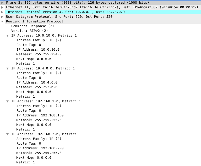
A packet capture performed on R1’s Gi0/1 interface confirms that a total of four prefixes are present in the RIPv2 Update packet.
R2’s RIPv2 database confirms the prefixes received by R1.
1
2
3
4
5
6
7
8
9
10
11
12
13
R2#show ip rip database
10.0.0.0/8    auto-summary
10.0.0.0/30    directly connected, GigabitEthernet0/1
10.0.10.0/23
    [1] via 10.0.0.1, 00:00:01, GigabitEthernet0/1
10.4.0.0/14
    [1] via 10.0.0.1, 00:00:01, GigabitEthernet0/1
192.168.1.0/24    auto-summary
192.168.1.0/24
    [1] via 10.0.0.1, 00:00:01, GigabitEthernet0/1
192.168.2.0/24    auto-summary
192.168.2.0/24
    [1] via 10.0.0.1, 00:00:01, GigabitEthernet0/1
A summary of the behavior imposed on all 6 of R1’s up/up Layer 3 interfaces can be found in the table below:
| Prefix | Behavior |
|---|---|
| 10.0.0.0/30 | Not summarized, not advertised |
| 192.168.1.0/24 | Not summarized, advertised as-is |
| 192.168.2.0/25 | Summarized into 192.168.2.0/24, advertised |
| 192.168.2.128/25 | Summarized into 192.168.2.0/24, advertised |
| 10.0.10.0/23 | Not summarized, advertised as-is |
| 10.4.0.0/14 | Not summarized, advertised as-is |
We can confirm that RIPv2’s auto-summary feature is causing classless networks 192.168.2.0/25 and 192.168.2.128/25 to be summarized into a Class C 192.168.2.0/24 network by removing the default auto-summary configuration from the RIPv2 process on R1.
1
2
3
4
5
6
R1#configure terminal
Enter configuration commands, one per line.  End with CNTL/Z.
R1(config)#router rip
R1(config-router)#no auto-summary
R1(config-router)#end
R1#
The output of show ip protocols confirms that RIPv2 is not performing automatic network summarization.
1
2
3
4
R1#show ip protocols | include rip|summarization
Routing Protocol is "rip"
  Redistributing: rip
  Automatic network summarization is not in effect    <<<
Now, let’s reactivate RIPv2 debugs on R1 to see how many prefixes are being advertised.
1
2
3
4
5
6
7
8
9
10
11
12
R1#debug ip rip
RIP protocol debugging is on
R1#
*Dec 28 03:18:10.614: RIP: sending v2 update to 224.0.0.9 via GigabitEthernet0/1 (10.0.0.1)
*Dec 28 03:18:10.615: RIP: build update entries
*Dec 28 03:18:10.615: 	10.0.10.0/23 via 0.0.0.0, metric 1, tag 0
*Dec 28 03:18:10.615: 	10.4.0.0/14 via 0.0.0.0, metric 1, tag 0
*Dec 28 03:18:10.616: 	192.168.1.0/24 via 0.0.0.0, metric 1, tag 0
*Dec 28 03:18:10.616: 	192.168.2.0/25 via 0.0.0.0, metric 1, tag 0
*Dec 28 03:18:10.616: 	192.168.2.128/25 via 0.0.0.0, metric 1, tag 0
R1#undebug all
All possible debugging has been turned off
We see all 5 expected prefixes inserted in the RIPv2 update. Checking R2’s RIP database, we can also see all 5 prefixes present in the database.
1
2
3
4
5
6
7
8
9
10
11
12
13
14
15
R2#show ip rip database
10.0.0.0/8    auto-summary
10.0.0.0/30    directly connected, GigabitEthernet0/1
10.0.10.0/23
    [1] via 10.0.0.1, 00:00:07, GigabitEthernet0/1
10.4.0.0/14
    [1] via 10.0.0.1, 00:00:07, GigabitEthernet0/1
192.168.1.0/24    auto-summary
192.168.1.0/24
    [1] via 10.0.0.1, 00:00:07, GigabitEthernet0/1
192.168.2.0/24    auto-summary
192.168.2.0/25
    [1] via 10.0.0.1, 00:00:07, GigabitEthernet0/1
192.168.2.128/25
    [1] via 10.0.0.1, 00:00:07, GigabitEthernet0/1
Finally, let’s confirm that all 5 prefixes are present in R2’s routing table.
1
2
3
4
5
6
7
8
9
10
11
12
13
14
15
16
17
18
19
20
R2#show ip route rip
Codes: L - local, C - connected, S - static, R - RIP, M - mobile, B - BGP
       D - EIGRP, EX - EIGRP external, O - OSPF, IA - OSPF inter area
       N1 - OSPF NSSA external type 1, N2 - OSPF NSSA external type 2
       E1 - OSPF external type 1, E2 - OSPF external type 2
       i - IS-IS, su - IS-IS summary, L1 - IS-IS level-1, L2 - IS-IS level-2
       ia - IS-IS inter area, * - candidate default, U - per-user static route
       o - ODR, P - periodic downloaded static route, H - NHRP, l - LISP
       a - application route
       + - replicated route, % - next hop override, p - overrides from PfR

Gateway of last resort is not set

      10.0.0.0/8 is variably subnetted, 4 subnets, 4 masks
R        10.0.10.0/23 [120/1] via 10.0.0.1, 00:00:23, GigabitEthernet0/1
R        10.4.0.0/14 [120/1] via 10.0.0.1, 00:00:23, GigabitEthernet0/1
R     192.168.1.0/24 [120/1] via 10.0.0.1, 00:00:23, GigabitEthernet0/1
      192.168.2.0/25 is subnetted, 2 subnets
R        192.168.2.0 [120/1] via 10.0.0.1, 00:00:23, GigabitEthernet0/1
R        192.168.2.128 [120/1] via 10.0.0.1, 00:00:23, GigabitEthernet0/1
The best explanation for this behavior can be found in the “Configuring Routing Information Protocol” chapter of the IP Routing: RIP Configuration Guide for Cisco IOS Release 15M&T. Under the “RIP Route Summarization” heading, the guide states that automatic summarization happens “by summarizinig subprefixes to the classful network boundary when crossing classful network boundaries.” Furthermore, under the “Summarizing RIP Routes” heading, the guide states the following:
“RIP Version 2 supports automatic route summarization by default. The software summarizes subprefixes to the classful network boundary when classful network boundaries are crossed. If you have disconnected subnets, disable automatic route summarization to advertise the subnets. When route summarization is disabled, the software sends subnet and host routing information across classful network boundaries.”
To best understand this, we must first understand what a classful network boundary is. Classful networks are an addressing architecture introduced by RFC 791 Section 2.3. They are described as follows:
“There are three formats or classes of internet addresses: in class a, the high order bit is zero, the next 7 bits are the network, and the last 24 bits are the local address; in class b, the high order two bits are one-zero, the next 14 bits are the network and the last 16 bits are the local address; in class c, the high order three bits are one-one-zero, the next 21 bits are the network and the last 8 bits are the local address.”
RFC 790 provides additional details about the IP addresses included in each class. The resulting class address ranges are described by the table below. Note that this table includes reserved subnets, as RIPv2 does not discriminate between reserved addresses and unreserved addresses. In the “Binary Addressing” field, an N indicates a network bit (that is, the section of the binary address that is the “network” portion of the address) while an L indicates a local bit (that is, the section of the binary address that is the “local” portion of the address.)
| Class Name | Binary Addressing | Lowest Valid Subnet | Highest Valid Subnet |
|---|---|---|---|
| Class A | 0NNNNNNN.LLLLLLLL.LLLLLLLL.LLLLLLLL | 1.0.0.0/8 | 127.0.0.0/8 |
| Class B | 10NNNNNN.NNNNNNNN.LLLLLLLL.LLLLLLLL | 128.0.0.0/16 | 191.255.0.0/16 |
| Class C | 110NNNNN.NNNNNNNN.NNNNNNNN.LLLLLLLL | 192.0.0.0/24 | 223.255.255.0/24 |
Individual organizations (such as businesses, universities, etc.) were originally assigned classful networks to use. However, individual organizations often connected to and required networking between each other. Since classful boundaries were typically cleanly split between organizations, RIPv2’s automatic summarization feature assisted with reducing the size of routing tables and RIPv2 update packet sizes with minimal effort needed on the part of the network administrators. This was especially important during the early ages of the Internet, as the processing and memory capabilities of routers were much scarcer than they are today.
To accomplish this, rules needed to be implemented in software to have this feature work intelligently. The Cisco IOS implementation of RIPv2’s automatic route summarization is essentially as follows:
- If RIPv2 has multiple subprefixes within a classful boundary in the RIP database and needs to send an update message out of an interface owning a subprefix within the same classful boundary, then RIPv2 will not perform automatic network summarization.
- In our example, R1 has 10.4.0.0/14 and 10.0.10.0/23 present in the RIP database. It needs to send an update out of Gi0/1, which has an IP address of 10.0.0.1 in the 10.0.0.0/30 network. All three of these networks are subprefixes of the Class A 10.0.0.0/8 network. Since RIPv2 needs to send an update out of Gi0/1 (10.0.0.1), R1 will not automatically summarize 10.4.0.0/14 and 10.0.10.0/23 to 10.0.0.0/8.
- If RIPv2 has multiple subprefixes within a classful boundary in the RIP database and needs to send an update message out of an interface that has an IP address within a different classful boundary, then RIPv2 will perform automatic network summarization.
- For example, let’s say a new interface Gi0/2 is created. This interface has an IP address of 11.0.0.1/30, connects to a third router, and is activated in the RIP process with
network 11.0.0.0configuration. RIPv2 will automatically summarize 10.4.0.0/14, 10.0.10.0/23, and 10.0.0.0/30 into a single 10.0.0.0/8 classful prefix that is advertised out the Gi0/2 interface towards the third router.
- For example, let’s say a new interface Gi0/2 is created. This interface has an IP address of 11.0.0.1/30, connects to a third router, and is activated in the RIP process with
RIPv2’s automatic summarization feature is often misunderstood - I hope that this helped you understand it better!