Deep Dive - IEEE 802.1D Spanning Tree Topology Change
While reviewing the IEEE 802.1D Spanning Tree Protocol Topology Change Notification mechanism, I felt some confusion as to the exact behavior that each bridge exhibits when a topology change occurs. This post documents my journey to alleviate this confusion in the lab!
Scope
During my CCIE studies, I understood that there were two types of BPDUs - a Configuration BPDU and a Topology Change Notification BPDU. However, I was unclear which bridges create which BPDU in a topology change scenario. Specifically, I wanted to clarify the following points:
When a topology change occurs on a non-root bridge (such as in the event of a link flap), what type of BPDU does that bridge create?
When an intermediate bridge receives a topology change notification from a downstream bridge, what type of BPDU is sent towards the root bridge, and what type of BPDU is sent towards the downstream bridge?
When a topology change occurs in a spanning tree, what type of BPDU do bridges not in the path of the topology change notification receive?
To answer these questions, I decided to test in the lab!
Topology

Bridge ID and IP address information is as follows:
| Node Name | Bridge ID | IP Address |
|---|---|---|
| Root | 5e00.0000.0000 | 192.168.1.1 |
| S1-1 | 5e00.0001.0000 | 192.168.1.100 |
| S2-1 | 5e00.0002.0000 | 192.168.1.103 |
| S1-2 | 5e00.0003.0000 | 192.168.1.101 |
| S1-3 | 5e00.0004.0000 | 192.168.1.102 |
| S2-2 | 5e00.0005.0000 | 192.168.1.104 |
| S2-3 | 5e00.0006.0000 | 192.168.1.105 |
| H1-1 | N/A | 192.168.1.10 |
| H1-2 | N/A | 192.168.1.20 |
| H2-1 | N/A | 192.168.1.30 |
| H2-2 | N/A | 192.168.1.40 |
Lab Materials
This lab was completed with a VIRL 1.6.65 server using the following nodes:
| Node Name | Operating System | Version |
|---|---|---|
| IOSv | IOS | 15.7(3)M3 |
| IOSvL2 | IOS | 15.2 |
Default Configuration
By default, all nodes were configured with their hostname, as well as the following configuration:
1
2
3
4
5
6
7
8
9
10
11
no ip domain-lookup
service timestamps debug datetime msec
service timestamps log datetime msec
logging buffered 10000000

interface GigabitEthernet0/0
  shutdown

line console 0
  exec-timeout 0 0
  logging synchronous
After all nodes came online, their clock was manually set to the same time with the clock set global EXEC command. However, the time of the clocks drifted during the lab, so not all debug or log timestamps are synchronized across devices.
Lab
We will attempt to answer our questions with the above topology through a link flap on S1-2’s Gi0/2 interface towards H1-1 while relevant debugs are running on S1-2, S1-1, Root, and S2-1.
First, let’s configure the switch named “Root” as the root bridge for VLAN 1. By default, it should already be the root bridge as a result of its bridge ID, but we will manually configure its priority anyway.
1
2
3
4
5
6
7
8
9
10
11
12
13
14
15
16
17
18
19
20
21
22
Root#configure terminal
Enter configuration commands, one per line.  End with CNTL/Z.
Root(config)#spanning-tree vlan 1 root primary
Root(config)#end
Root#show spanning-tree vlan 1

VLAN0001
  Spanning tree enabled protocol ieee
  Root ID    Priority    24577
             Address     5e00.0000.0000
             This bridge is the root
             Hello Time   2 sec  Max Age 20 sec  Forward Delay 15 sec

  Bridge ID  Priority    24577  (priority 24576 sys-id-ext 1)
             Address     5e00.0000.0000
             Hello Time   2 sec  Max Age 20 sec  Forward Delay 15 sec
             Aging Time  300 sec

Interface           Role Sts Cost      Prio.Nbr Type
------------------- ---- --- --------- -------- --------------------------------
Gi0/1               Desg FWD 4         128.2    P2p
Gi0/2               Desg FWD 4         128.3    P2p
Next, let’s review the debugs we need to enable. On S1-2, Root, and S2-1, we will want to see Spanning Tree topology events as well as BPDUs that are sent and received.
1
2
3
4
5
6
7
8
9
10
11
12
13
14
15
16
17
18
19
20
21
22
23
24
25
26
27
28
29
30
31
32
33
34
35
Root#debug spanning-tree ?
  all              All Spanning Tree debugging messages
  bpdu             Spanning tree BPDU              <<<
  bpdu-opt         Optimized BPDU handling
  config           Spanning tree config changes    <<<
  etherchannel     EtherChannel support
  events           Spanning tree topology events
  exceptions       Spanning tree exceptions
  general          Spanning tree general
  mstp             MSTP debug commands
  pvst+            PVST+ events
  root             Spanning tree root events
  snmp             Spanning Tree SNMP handling
  switch           Switch Shim debug commands
  synchronization  STP state sync events

Root#debug spanning-tree events
Spanning Tree event debugging is on
Root#debug spanning-tree bpdu
Root#

S1-1#debug spanning-tree events
Spanning Tree event debugging is on
S1-1#debug spanning-tree bpdu
S1-1#

S1-2#debug spanning-tree events
Spanning Tree event debugging is on
S1-2#debug spanning-tree bpdu
S1-2#

S2-1#debug spanning-tree events
Spanning Tree event debugging is on
S2-1#debug spanning-tree bpdu
S2-1#
Now, let’s shut down S1-2’s Gi0/2, causing a topology change.
1
2
3
4
S1-2#configure terminal
S1-2(config)#interface GigabitEthernet0/2
S1-2(config-if)#shutdown
S1-2(config-if)#end
After waiting for the topology to stabilize, let’s shut off the debugs on each device.
1
2
3
4
5
6
7
8
9
10
11
Root#undebug all
All possible debugging has been turned off

S1-1#undebug all
All possible debugging has been turned off

S1-2#undebug all
All possible debugging has been turned off

S2-1#undebug all
All possible debugging has been turned off
Now, let’s review the debugs sent to S1-2’s logfile. Note that the “Dec.14.14:38:27” regular expression only shows us debugs that occurred immediately after the Gi0/2 interface was shutdown.
1
2
3
4
5
6
7
8
9
10
11
12
13
14
15
S1-2#show logging | begin Dec.14.14:38:27
<snip>
1 | Dec 14 14:38:27.613: STP: VLAN0001 rx BPDU: config protocol = ieee, packet from GigabitEthernet0/1  , linktype IEEE_SPANNING , enctype 2, encsize 17    <<<-|
2 | Dec 14 14:38:27.614: STP: enc 01 80 C2 00 00 00 FA 16 3E D2 06 2C 00 26 42 42 03                                                                        <<< |
3 | Dec 14 14:38:27.621: STP: Data     000000000060015E00000000000000000480015E000001000080030100140002000F00                                               <<< |- 1.
4 | Dec 14 14:38:27.634: STP: VLAN0001 Gi0/1:0000 00 00 00 60015E0000000000 00000004 80015E0000010000 8003 0100 1400 0200 0F00                              <<< |
5 | Dec 14 14:38:27.648: STP(1) port Gi0/1 supersedes 0                                                                                                     <<<-|

1 | Dec 14 14:38:27.649: STP: VLAN0001 Gi0/2 tx BPDU: config protocol=ieee                                                                                  <<<-|- 2.
2 |     Data : 0000 00 00 00 60015E0000000000 00000008 80015E0000030000 8003 0200 1400 0200 0F00                                                            <<<-|

1 | Dec 14 14:38:28.683: STP: VLAN0001 Gi0/1 tx BPDU: tcn: 0000 00 80                                                                                       <<<-|- 3.

1 | Dec 14 14:38:28.685: STP: VLAN0001 sent Topology Change Notice on Gi0/1                                                                                 <<<-|- 4.
2 | Dec 14 14:38:28.685: STP[1]: Generating TC trap for port GigabitEthernet0/2                                                                             <<<-|
The debugs show that four separate events occurred on S1-2. I visually segregated these events to make it easier to visualize. To the right of each debug is each logical event. To the left of each debug is an individual line number that I will refer to for more detail.
The four events are:
S1-2 receives a Configuration BPDU on Gi0/1 originated by the root bridge (Root) and passed on by S1-1. This makes sense, as Gi0/1 is our root port. The debug in line 4 shows us the contents of this Configuration BPDU and logically separates it into each section of the BPDU to make it easier to read (unlike line 3, which lumps everything together). The fourth section in line 4 is the “BPDU Flags” section, which is a 2-byte field containing the Topology Change Acknowledgment flag and the Topology Change flag. Since both of these values are set to zero, this tells us that this Configuration BPDU was originated before the topology change (that is, the flapping of Gi0/2) occurred. As such, for our purposes, we can ignore it.
S1-2 generates a Configuration BPDU on Gi0/2 (the interface that was just administratively shut down). At first, this might not make sense (after all, why would Spanning Tree attempt to send a Configuration BPDU out of an interface that is down?) However, since the Spanning Tree process on S1-2 has not yet sent a Topology Change Notification BPDU towards the root bridge, the Spanning Tree process is most likely not yet aware that the Gi0/2 interface is down at the moment. As a result, Spanning Tree would likely hand the Configuration BPDU generated in this debug to the data plane, which would subsequently drop it since it cannot forward a frame out of an interface that is down.
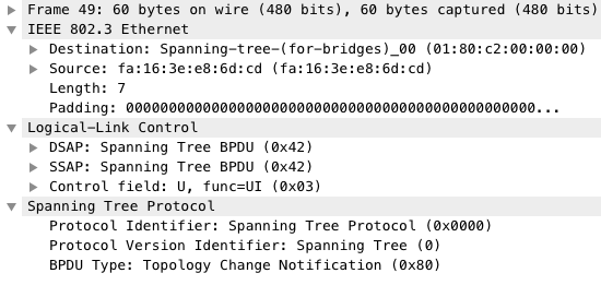
About a second later, S1-2 generates a Topology Change Notification BPDU out of Gi0/1. This indicates that the Spanning Tree process is now aware that Gi0/2 is down, and that a topology change has occurred. Just like the debug on the fourth line of the first event, this debug logically separates each part of the BPDU to make it easier to read. In this debug, the third section is set to
0x80. This indicates that this is a Topology Change Notification BPDU. This stands in contrast to the0x00value seen in line four of the first event, which indicates the BPDU is a Configuration BPDU.Finally, the Spanning Tree process reports that it has sent a Topology Change Notification (in this case, the debug calls it a “Notice”) out of the root port, Gi0/1.
The screenshot below shows the exact Topology Change Notification BPDU generated by S1-2 that is sent out of the Gi0/1 interface from a Wireshark perspective.
Next, we must search through S1-1’s debugs to find when it receives this Topology Change Notification BPDU, as well as what it does with it.
1
2
3
4
5
6
7
8
9
10
11
12
13
S1-1#show logging | begin Dec.14.14:38
<snip>
1 | Dec 14 14:38:12.185: STP: VLAN0001 rx BPDU: config protocol = ieee, packet from GigabitEthernet0/2  , linktype IEEE_SPANNING , enctype 2, encsize 17    <<<-|
2 | Dec 14 14:38:12.187: STP: enc 01 80 C2 00 00 00 FA 16 3E E8 6D CD 00 07 42 42 03                                                                        <<< |
3 | Dec 14 14:38:12.193: STP: Data     00000080                                                                                                             <<< |- 1.
4 | Dec 14 14:38:12.194: STP: VLAN0001 Gi0/2:0000 00 80                                                                                                     <<< |
5 | Dec 14 14:38:12.196: STP: VLAN0001 Topology Change rcvd on Gi0/2                                                                                        <<<-|

1 | Dec 14 14:38:12.198: STP: VLAN0001 Gi0/1 tx BPDU: tcn: 0000 00 80                                                                                       <<<-|- 2.
2 | Dec 14 14:38:12.200: STP: VLAN0001 sent Topology Change Notice on Gi0/1                                                                                 <<<-|

1 | Dec 14 14:38:12.201: STP: VLAN0001 Gi0/2 tx BPDU: config protocol=ieee                                                                                  <<<-|- 3.
2 |     Data : 0000 00 00 80 60015E0000000000 00000004 80015E0000010000 8003 0200 1400 0200 0F00                                                            <<<-|
These debugs show three separate events that occurred on S1-1:
S1-1 receives the Topology Change Notification BPDU from Gi0/2, as shown by line 1. You can tell that this is the Topology Change Notification BPDU sent by S1-2 because of the
0x80value in the third field of the BPDU shown in line 4. S1-1 recognizes this as a Topology Change Notification BPDU and logs it as such in line 5.Before doing anything else, S1-1 creates a new Topology Change Notification BPDU and sends it out of Gi0/1 (the bridge’s root port) towards Root. Line 1 shows the contents of this BPDU.
Finally, S1-1 sends a Configuration BPDU out of Gi0/2 towards S1-2 with a value of
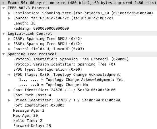
0x80in the fourth field, as shown by line 2. If you convert0x80to binary, you get1000 0000. The most significant bit of the BPDU Flags field is the “Topology Change Acknowledgment” bit. As such, this Configuration BPDU is informing the downstream bridge (S1-2) that the Topology Change Notification BPDU has been received. If S1-2 did not receive this BPDU, S1-2 would continue sending Topology Change Notification BPDUs at the expiration of each Hello timer (that is, every 2 seconds by default).
Take a second to think about why S1-1 chooses to send a Topology Change Notification BPDU to the root bridge before sending an acknowledgment to S1-2 that S1-2’s Topology Change Notification BPDU was received. From a protocol philosophy perspective, this makes perfect sense. If you were designing a hierarchical protocol that needs to rapidly react to a topology change, and you made the decision that the head of the hierarchy (in this case, the root bridge) is responsible for propagating information about the topology change, you would want hierarchy members (bridges) to inform the hierarchy head (root bridge) about the change as rapidly as possible so that the rest of the hierarchy can react to the topology change. Therefore, when an intermediate bridge receives the news that a topology change has occurred from a downstream bridge, the bridge should prioritize passing along the news towards the root bridge over acknowledging receipt of the news.
The screenshot below shows the Configuration BPDU with the “Topology Change Acknowledgment” flag set that is sent from S1-1 to S1-2 from a Wireshark perspective.
Now, let’s review Root’s debugs to find when it receives the Topology Change Notification BPDU originated by S1-1.
1
2
3
4
5
6
7
8
9
10
11
12
Root#show logging | begin Dec.14.14:38
<snip>
1 | Dec 14 14:38:34.702: STP: VLAN0001 rx BPDU: config protocol = ieee, packet from GigabitEthernet0/1  , linktype IEEE_SPANNING , enctype 2, encsize 17    <<<-|
2 | Dec 14 14:38:34.703: STP: enc 01 80 C2 00 00 00 FA 16 3E DD 98 A1 00 07 42 42 03                                                                        <<< |- 1.
3 | Dec 14 14:38:34.711: STP: VLAN0001 Gi0/1:0000 00 80                                                                                                     <<< |
4 | Dec 14 14:38:34.713: STP: VLAN0001 Topology Change rcvd on Gi0/1                                                                                        <<<-|

1 | Dec 14 14:38:34.715: STP: VLAN0001 Gi0/1 tx BPDU: config protocol=ieee                                                                                  <<<-|- 2.
2 |     Data : 0000 00 00 81 60015E0000000000 00000000 60015E0000000000 8002 0000 1400 0200 0F00                                                            <<<-|

1 | Dec 14 14:38:35.622: STP: VLAN0001 Gi0/2 tx BPDU: config protocol=ieee                                                                                  <<<-|- 3.
2 |     Data : 0000 00 00 01 60015E0000000000 00000000 60015E0000000000 8003 0000 1400 0200 0F00                                                            <<<-|
These debugs show three separate events that occurred on Root:
Root receives the Topology Change Notification BPDU from Gi0/1, as shown by line 1. You can tell that this is the Topology Change Notification BPDU sent by S1-1 because of the
0x80value in the third field of the BPDU shown in line 3. Root recognizes this as a Topology Change Notification BPDU and logs it as such in line 4.Root sends a Configuration BPDU out of Gi0/1 with the Topology Change Acknowledgment and Topology Change bits set in the BPDU Flags field. As shown in line 2, the fourth section of the BPDU has a value of
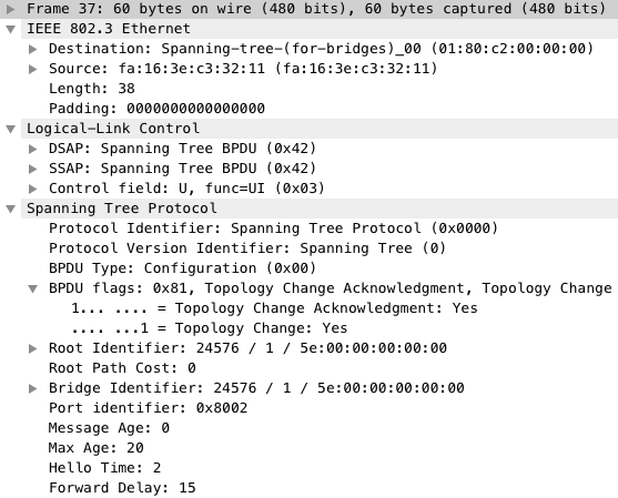
0x81. If you convert0x81to binary, you get1000 0001. The most significant bit of the BPDU Flags field is the “Topology Change Acknowledgment” bit, while the least significant bit of the BPDU Flags field is the “Topology Change” bit. Root is sending a Configuration BPDU to S1-2 acknowledging that it received S1-2’s Topology Change Notification BPDU, as well as informing it that there was a change in the topology of the spanning tree.Root sends a Configuration BPDU out of Gi0/2 with the Topology Change bit set in the BPDU Flags field. As shown in line 2, the fourth section of the BPDU has a value of
0x01. If you convert0x01to binary, you get0000 0001. The least significant bit of the BPDU Flags field is the “Topology Change” bit. Root is sending a Configuration BPDU towards S2-1 stating that there was a change in the topology of this spanning tree.
The screenshot below shows the Configuration BPDU with the “Topology Change Acknowledgment” and “Topology Change” bits set sent from Root to S1-1 from a Wireshark perspective.
If we take a look at S1-1 once more, we see debugs with three different events. The first event indicates that S1-1 received the Configuration BPDU from Root on Gi0/1 with the “Topology Change Acknowledgment” and “Topology Change” bits set. The second and third events indicate that S1-1 sends Configuration BPDUs out of Gi0/2 (towards S1-2) and Gi0/3 (towards S1-3) with the “Topology Change” bit set.
1
2
3
4
5
6
7
8
9
10
11
1 | Dec 14 14:38:12.215: STP: VLAN0001 rx BPDU: config protocol = ieee, packet from GigabitEthernet0/1  , linktype IEEE_SPANNING , enctype 2, encsize 17    <<<-|
2 | Dec 14 14:38:12.216: STP: enc 01 80 C2 00 00 00 FA 16 3E C3 32 11 00 26 42 42 03                                                                        <<< |
3 | Dec 14 14:38:12.222: STP: Data     000000008160015E00000000000000000060015E000000000080020000140002000F00                                               <<< |- 1.
4 | Dec 14 14:38:12.231: STP: VLAN0001 Gi0/1:0000 00 00 81 60015E0000000000 00000000 60015E0000000000 8002 0000 1400 0200 0F00                              <<< |
5 | Dec 14 14:38:12.240: STP(1) port Gi0/1 supersedes 0                                                                                                     <<<-|

1 | Dec 14 14:38:12.242: STP: VLAN0001 Gi0/3 tx BPDU: config protocol=ieee                                                                                  <<<-|- 2.
2 |     Data : 0000 00 00 01 60015E0000000000 00000004 80015E0000010000 8004 0100 1400 0200 0F00                                                            <<<-|

1 | Dec 14 14:38:13.219: STP: VLAN0001 Gi0/2 tx BPDU: config protocol=ieee                                                                                  <<<-|- 3.
2 |     Data : 0000 00 00 01 60015E0000000000 00000004 80015E0000010000 8003 0100 1400 0200 0F00                                                            <<<-|
Debugs from S2-1 indicate that S2-1 also receives a Configuration BPDU from Root - however, only the “Topology Change” bit is set.
1
2
3
4
5
6
7
8
9
10
11
12
13
S2-1#show logging | beg Dec.14.14:38:28
<snip>
1 | Dec 14 14:38:28.547: STP: VLAN0001 rx BPDU: config protocol = ieee, packet from GigabitEthernet0/1  , linktype IEEE_SPANNING , enctype 2, encsize 17    <<<-|
2 | Dec 14 14:38:28.548: STP: enc 01 80 C2 00 00 00 FA 16 3E 12 11 90 00 26 42 42 03                                                                        <<< |
3 | Dec 14 14:38:28.555: STP: Data     000000000160015E00000000000000000060015E000000000080030000140002000F00                                               <<< |- 1.
4 | Dec 14 14:38:28.567: STP: VLAN0001 Gi0/1:0000 00 00 01 60015E0000000000 00000000 60015E0000000000 8003 0000 1400 0200 0F00                              <<< |
5 | Dec 14 14:38:28.579: STP(1) port Gi0/1 supersedes 0                                                                                                     <<<-|

1 | Dec 14 14:38:28.581: STP: VLAN0001 Gi0/2 tx BPDU: config protocol=ieee                                                                                  <<<-|- 2.
2 |     Data : 0000 00 00 01 60015E0000000000 00000004 80015E0000020000 8003 0100 1400 0200 0F00                                                            <<<-|

1 | Dec 14 14:38:28.592: STP: VLAN0001 Gi0/3 tx BPDU: config protocol=ieee                                                                                  <<<-|- 3.
2 |     Data : 0000 00 00 01 60015E0000000000 00000004 80015E0000020000 8004 0100 1400 0200 0F00                                                            <<<-|
The screenshot below shows the Configuration BPDU with only the “Topology Change” bit set sent from Root to S2-1 from a Wireshark perspective.

Let’s turn back to Root’s debugs to confirm how long Root will send Configuration BPDUs with the “Topology Change” bit set. The previous debugs from Root show that the first Configuration BPDUs were sent at 14:38:34.715. The below debugs show that the last debug with the “Topology Change” bit set is sent at 14:39:08.120. This shows that Root indicated a topology change was underway for about 34 seconds. This roughly equates to the sum of the Maximum Age timer (20 seconds) and the Forwarding Delay timer (15 seconds), which is expected behavior as documented in Cisco’s “Understanding Spanning-Tree Protocol Topology Changes” Troubleshooting TechNote.
1
2
3
4
5
6
7
8
9
Dec 14 14:39:08.105: STP: VLAN0001 Gi0/1 tx BPDU: config protocol=ieee
    Data : 0000 00 00 01 60015E0000000000 00000000 60015E0000000000 8002 0000 1400 0200 0F00
Dec 14 14:39:08.120: STP: VLAN0001 Gi0/2 tx BPDU: config protocol=ieee
    Data : 0000 00 00 01 60015E0000000000 00000000 60015E0000000000 8003 0000 1400 0200 0F00

Dec 14 14:39:10.135: STP: VLAN0001 Gi0/1 tx BPDU: config protocol=ieee
    Data : 0000 00 00 00 60015E0000000000 00000000 60015E0000000000 8002 0000 1400 0200 0F00
Dec 14 14:39:10.151: STP: VLAN0001 Gi0/2 tx BPDU: config protocol=ieee
    Data : 0000 00 00 00 60015E0000000000 00000000 60015E0000000000 8003 0000 1400 0200 0F00
Conclusion
In summary, we were able to determine the answers to our questions by invoking a topology change in an environment with debugs enabled. The answers to our questions are as follows:
When a topology change occurs on a non-root bridge, that bridge will create a Topology Change Notification BPDU and sent it out of the bridge’s Root Port towards the root bridge.
When an intermediate non-root bridge receives a Topology Change Notification BPDU from a downstream bridge, the intermediate bridge will relay the Topology Change Notification BPDU out of its respect Root Port to expedite the topology change process as a whole. Once that task is complete, the intermediate bridge will send a Configuration BPDU towards the downstream bridge that originated the Topology Change Notification BPDU with the “Topology Change Acknowledgment” bit sent to prevent further Topology Change Notification BPDUs from being created.
Bridges that are not in the path of the Topology Change Notification BPDU will eventually receive a Configuration BPDU originated by the root bridge with the “Topology Change” bit set. Upon receiving this BPDU, the bridge will rapidly age out MAC addresses by setting the age of each MAC address to the Forwarding Delay timer (15 seconds).
References
- “Understanding Spanning-Tree Protocol Topology Changes” Troubleshooting TechNote
- Chapter 3 (“Spanning Tree Protocol”) of the CCIE Routing and Switching v5.0 Official Cert Guide, Volume 1, Fifth Edition
- “Configuring STP” chapter of the Catalyst 3750 Switch Software Configuration Guide, Cisco IOS Release 16.0(2)SE and Later
I hope that this helps you understand the IEEE 802.1D Spanning Tree Protocol topology change mechanism slightly better!